5 x Control unit operation
38
FA ROTEX Solaris - 08/2007
5 Control
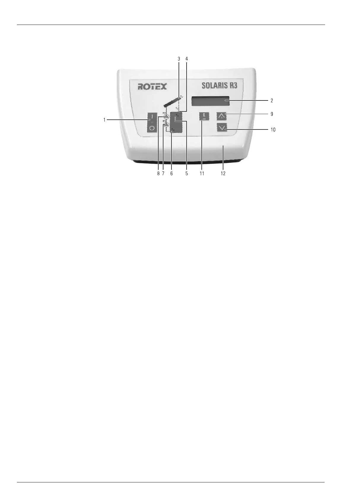
5.1 Operating and display elements
5.2 Controller operating principle
The Solaris system is operated throughout the year, without the need for manual intervention. Speed-controlled pump operation
is regulated by the Solaris R3 temperature difference controller. The operating and display elements are shown in Fig. 5-1.
5.2.1 Pump operation
Pump operation includes the following functions:
– Continuous measurement of the temperature difference between solar panel and return flow temperatures and a comparison
with the selected parameter "Delta T On".
– Pump switch-on, if this parameter is exceeded (e.g. return flow temperature is 40°C and "Delta T On" is 15 K; solar panel
temperature >55°C).
– Additional filling of the system with the upper booster pump (P2) as a function of the adjusted parameter value "Time P2"
in [s].
– If the correctly adjusted FlowSensor measures a stable flow before this time has elapsed, the Solaris system is
completely filled with water.
– Due to the siphon effect in the feed pipe of the solar circuit, only with the circulation pump P1. Pump output is regulated as
a function of the temperature difference between Solaris feed and return flow temperatures.
1 Main switch with indicator light
2 Display for showing temperature and
parameters (energy saving function:
Display illumination is switched off
10 minutes after the last key actuation)
3 Light for solar panel temperature display
4 Light for Solaris feed temperature and
flow measurement display (FLS)
5 Light for storage tank temperature
display
6 Light for solar return flow temperature
display
7 Operating state light for speed-
controlled circulation pump P1
(lights up when pump is operating)
8 Operating state light for booster pump
P2 (lights up when pump is operating;
flashes when pump is throttled)
9 Up arrow for moving the temperature or
parameter display up by one
setting/increasing parameter settings
10 Down arrow for moving the temperature
or parameter display down by one
setting/decreasing parameter settings
11 Information key for accessing the
information level (displays measured
values, maximum values and calculated
values) and OK key for confirming and
storing settings in the setting menu
12 Controller housing
13 Housing locking screws (device may only
be opened by an authorised specialist.
Disconnect from mains supply before
opening!)
Fig. 5-1 Operating and display elements