3 Phase Power Analyser / EN
23 09/30/16 Version No. 00
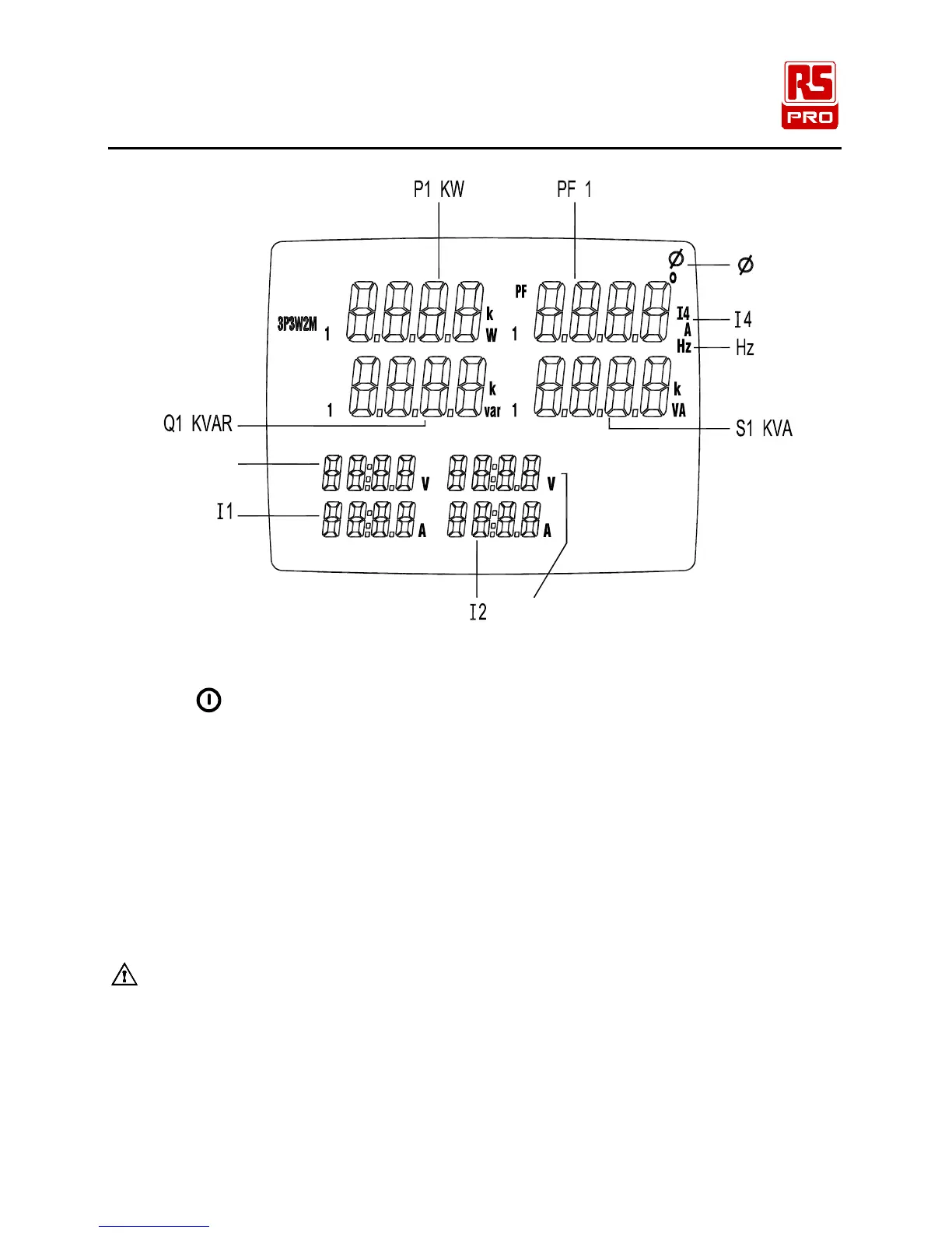
S
U23
Q
U12
P
Figure 10. 3P3W2M General Display
1. Press
key to turn on the instrument.
2. Press “WIRING” key to select the 3P3W2M electrical system test, the “3P3W2M” symbol will
be displayed.
3. Connect the voltage test leads and current probes to the instrument :
Connect the black voltage test lead to the “N” terminal.
Connect the red voltage test lead to the “U1” terminal.
Connect the yellow voltage test lead to the “U2” terminal.
Connect the I1 current probe to the “I1” socket.
Connect the I2 current probe to the “I2” socket.
4. Connect the voltage test leads and current probes to the electrical equipment to be tested as
shown in Figure 9. 3P3W2M Wiring Connection Diagram
CAUTION:
Where possible, isolate the power to the electrical circuit to be tested before
connecting the voltage test leads and current probes
Connect the black voltage test alligator to the Phase 2 “L2”.
Connect the red voltage test alligator to the Phase 1 “L1”.
Connect the yellow voltage test alligator to the Phase 3 “L3”.
Clamp the I1 current probe securely around Phase 1 “L1”
Clamp the I2 current probe securely around Phase 3 “L3”.
V2