VLT
Vertical Process Pump
28 V1.090418
6. Place two of the coupling bolts 180 degrees apart and tighten them progressively, closing
the gap between the spacer and the adjusting plate.
7. Insert the other two coupling bolts and tighten them.
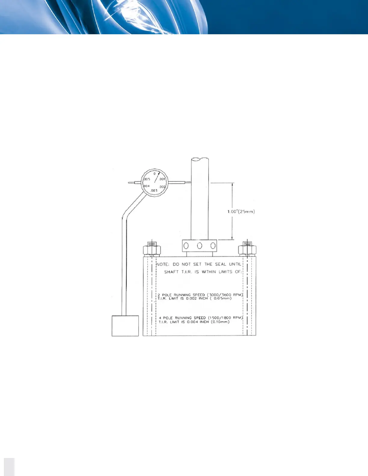
8. Attach the Total Indicator Readout (TIR) tool 1 inch above the mechanical seal, being
careful not to force the shaft radially, and turn the shaft. TIR measurement should not
surpass the following limits:
0.002 inch (0.05 mm) for pumps with a 2 pole running speed (3000/3600 RPM) driver.
0.004 inch (0.10 mm) for pumps with a 4 pole running speed (1500/1800 RPM) or
slower.
Figure 4.6 TIR tool setting diagram.
NOTE: If runout measurements exceed the above stated limits, remove the four coupling bolts placed
on steps 6 and 7 and rotate the spacer 180°. Place and retighten the bolts as stated in steps 6 and 7
and take new TIR measurements as stated in step 8. If runout measurements still exceed the stated
limits, rotate the spacer to a new position and repeat the TIR measurements.