O&M Manual –90E1720004
Section 5 Installation Page 15 of 52
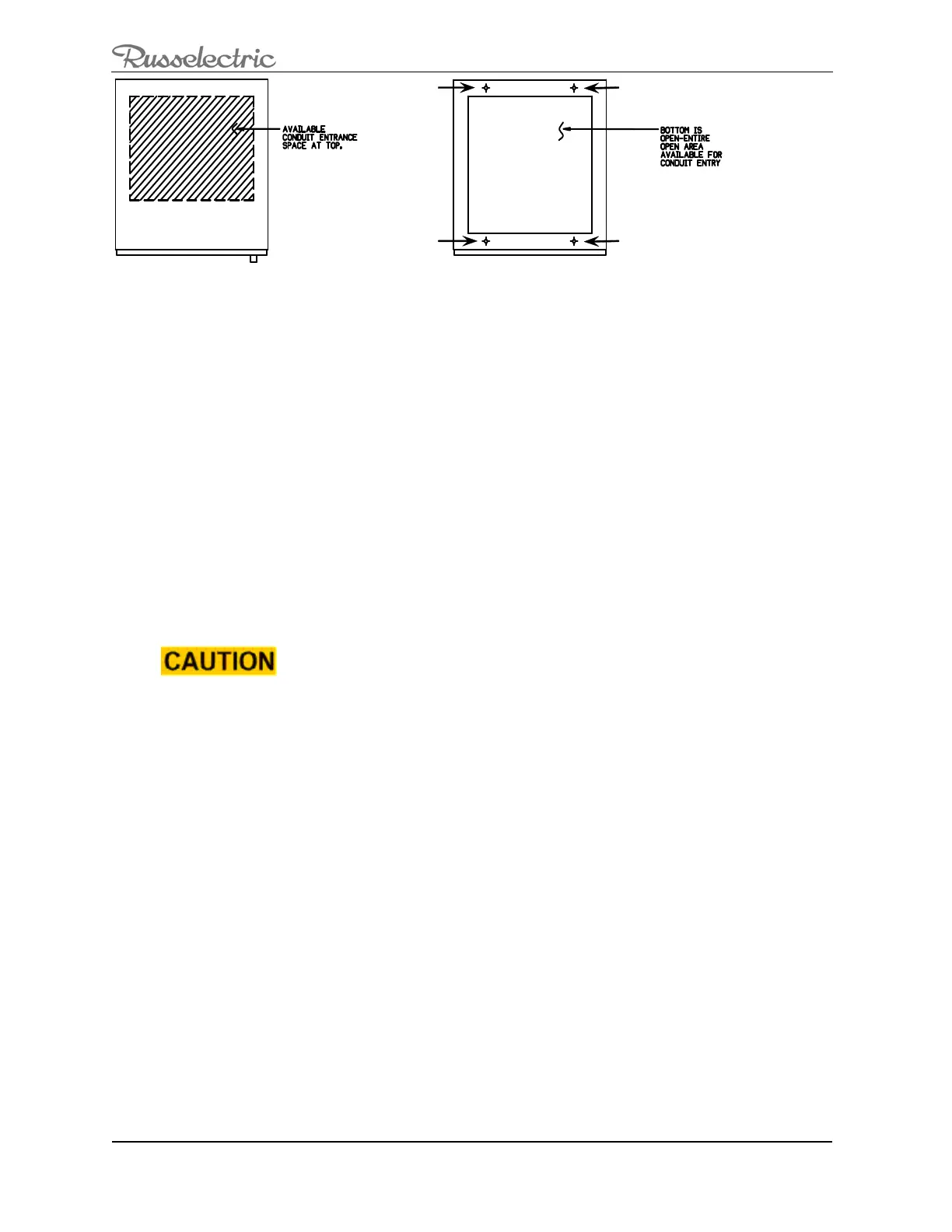
Figure 5: Anchoring the Switch.
Anchoring the Switch -Seismic
During an earthquake, the switch can move in any direction. Any incoming cables must
accommodate this motion. The switch enclosure should not be used to mount exterior
equipment. Any mounted equipment will negate seismic certification.
When anchoring for a seismic location:
1. Refer to a seismic study done by a certified engineer for proper anchor detail
information.
2. For proper anchoring performance, use 1/2-inch grade 5 anchoring hardware and
torque to 60 ft-lbs.
3. Use 1/2-inch bevel washers (furnished).
Connect the Power Cables, Controls, and Wiring
Connect the Power Cables
LOSS OF EQUIPMENT GROUND-FAULT PROTECTION
Do not connect grounding conductors to any load neutral
terminal(s).
Failure to follow this instruction can result in equipment damage.
NOTE: When connecting power cables, use 90 °C insulated conductors based on the ampacity
of 75 °C conductors unless otherwise indicated by supplemental instructions.
Russelectric bypass-isolation transfer switches are provided with compression or mechanical
type lugs for terminating the main power cables.
1. Determine the Source or Load and phase of each cable before making the
connection See Figure 6.
Note: Viewing the switch from the front, the pole sequence is phased N-A-B-C left-to-right.
Non-standard arrangements may be necessary to meet specific requirements. If so, the bus is
marked A, B, C, and N in the order specified by the customer. If an optional solid neutral is
provided, all the connections for the neutral are labeled.
2. Avoid sharp turns, corners, and edges when forming cables for termination
within the switch. This reduces the risk of damage to equipment or weakening of
the cable insulation. The cable manufacturer’s instructions should be followed in
determining the minimum bending radii of the cables. This will vary with the
 Loading...