O&M Manual –90E1720004
Section 2 Introduction Page 7 of 52
Section 2 Introduction
This manual contains instructions for the proper installation, operation and maintenance of
Russelectric bypass-isolation transfer switches.
The purchaser’s engineering, installation, and operating staff supervisors should familiarize
themselves with this manual and become acquainted with the appearance and characteristics of
each piece of equipment mounted or contained in the transfer switch.
These instructions and procedures apply to Russelectric bypass-isolation transfer switch
installations. When special features or non-standard components are incorporated in the
bypass/isolation transfer switch, detailed instructions for these components are included in the
equipment drawings specific to the project.
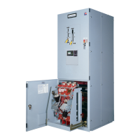
General Description
Russelectric bypass-isolation transfer switches are manufactured from formed channel
framework and code gauge sheet steel. All steel parts are prepared for painting by a five step
cleaning, phosphatizing and sealing process. The parts are then painted utilizing a polyester
powder coating applied by the electrostatic method and cured in a baking oven and is designed
to stand up to normal industrial environments. Russelectric Transfer Switches are listed to
UL1008, Underwriters Laboratories® (UL®).
Russelectric bypass-isolation transfer switches provide automatic or manual transfers between
the utility and an alternate source. The operating temperature of this equipment is 10-40°C.
Each bypass-isolation transfer switch is custom designed to specifications. Structures and bus
configurations are arranged according to customer specifications. Complete customer drawings
are furnished for each transfer switch assembly and should be reviewed before installing the
equipment. The drawings include elevation, one-line diagrams, control schematics and wiring
diagrams.
Extra features and special control options are often incorporated when specified by the
purchaser’s order. The special features are shown on the drawings and diagrams for the specific
transfer switch assembly. Instructions for the control panel can be found in the user’s manual.
 Loading...