O&M Manual –90E1720004
Section 5 Installation Page 21 of 52
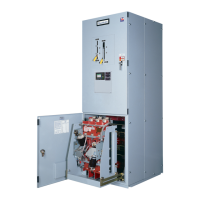
Transfer Switch Inspection and Testing Before Operation
After the Russelectric bypass-isolation transfer switch and components have been installed and
all control and primary connections made; perform a final inspection and test before placing the
switch into service.
When installed correctly, the bypass-isolation transfer switch conforms to the following
requirements:
1. Front panels and doors form a straight, true line; and when transformers and/or
other gear are included, the front panels line up or form parallel lines.
2. The switch is fastened securely to the floor channels or base pad.
3. Bus and control wiring connections are connected properly.
Directions for testing relays, instruments, meters, circuit breakers, and other electronic devices
that are included in the assembly are given in the instruction bulletin for each individual device.
Settings for protective devices are determined from a coordination study performed by the
purchaser, consultant, or provided by Russelectric. Factory settings are used for production
testing and may not reflect specific site requirements.
Selection of test equipment depends on the rating and type of installation. A multi-meter is
necessary to check the continuity of control circuits. A megohm meter is also needed for testing.
Check the Power Circuit Connections
Perform the following steps to check power circuits.
1. Check wire connections and bolted bus connections to confirm that no loosening
or damage occurred during shipment or installation. Immediately replace any
covers or barriers that were removed to check connections.
Note: Correct torque values are listed on labels located in the transfer switch enclosure and in
table 1 of this manual.
Check the External Equipment
Perform continuity checks for the connections to external equipment, such as remote controls,
interlock circuits, and auxiliary switches. Refer to the appropriate procedures in the instruction
bulletin for each individual device being tested.
Check the Auxiliary Equipment
Relays included on or in the instrument panels are set for manufacturing testing levels when
shipped.
1. Determine the final relay settings from a coordination study performed by the
purchaser, consultant, or provided by Russelectric.
2. Make necessary modifications to the relay settings according to the instruction
bulletin for that particular relay.
3. Circuit monitors and power meters included on the front of the equipment may
or may not be properly configured. The final configuration of these devices must
be set by the purchaser or consultant. Refer to the circuit monitor and power
meter instruction bulletins when setting these devices.
 Loading...