REPAIR HYDROSTATIC POWER TRAIN
2/12/97 6 - 39
M
L
J
N
O
K
A
D
E
F
G
H
I
B
C
34 N•m (25 lb-ft.)
20 N•m
(168 lb-in.)
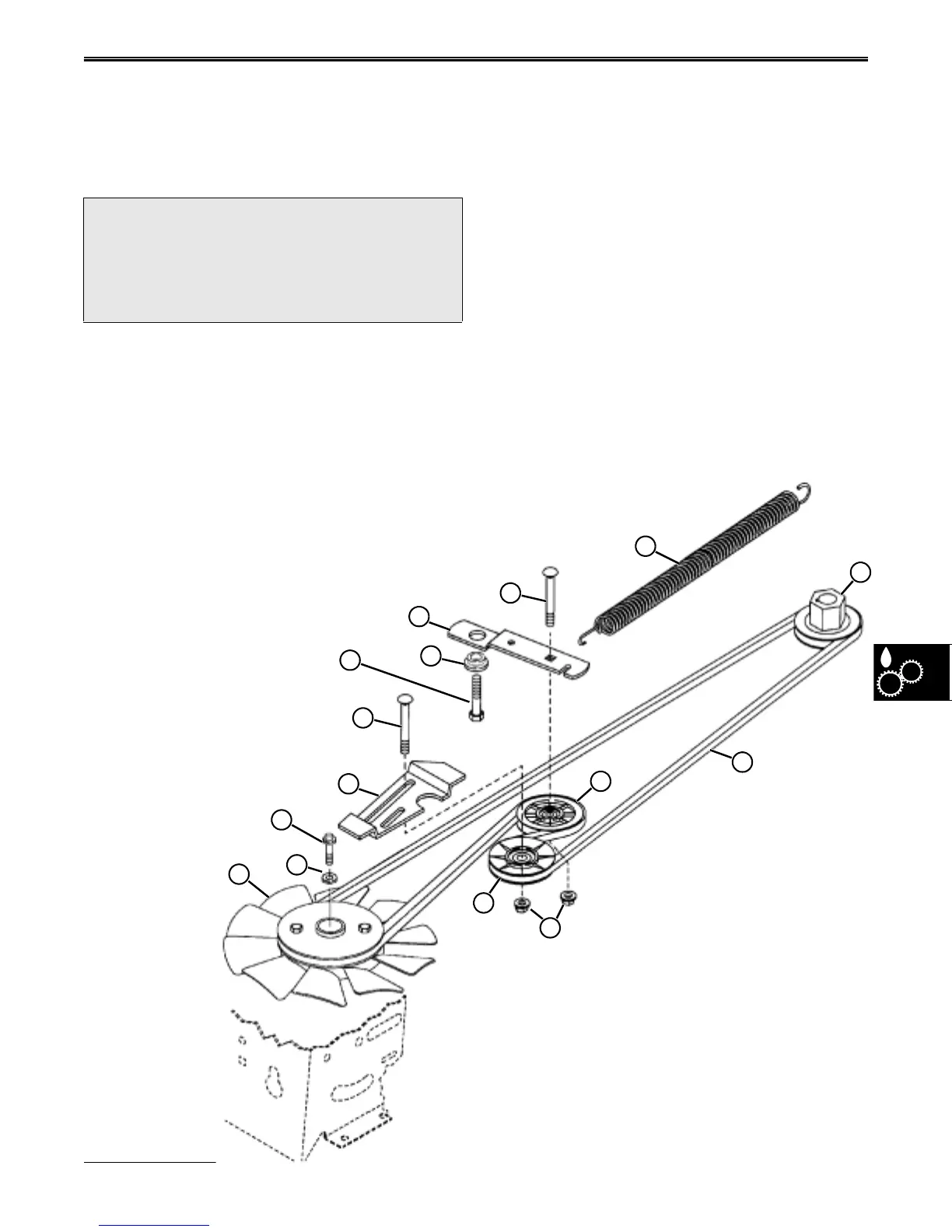
NOTE: To remove Transaxle drive sheave and
fan assembly (A) transaxle must be
lowered or completely removed from
tractor.
A. Transaxle drive sheave
B. Washer
C. Cap screw (M6x25)
D. Adjustable idler weldment bracket
E. Carriage bolt (M8x35)
F. Cap screw (M8x20)
G. Bushing
H. Bellcrank
I. Carriage bolt (M8x45)
J. Tensioning spring
K. Adjustable idler
L. Crankshaft drive sheave
M. Drive belt
N. Bellcrank idler
O. Flange nuts (M8)
TRACTION DRIVE BELT
TENSIONING SYSTEM REMOVAL/
INSPECTION/INSTALLATION—K55
1. Remove mower deck.
2. Remove Traction Drive Belt (See “TRACTION
DRIVE BELT REMOVAL—K55” on page 36)
3. Thread one end of a three foot long piece of starter
rope under the front hook of bellcrank tension
spring (J). Pull rope half way through spring until
ends meet, and wrap ends around a bar several
times to make a temporary handle. Pull handle until
spring hook is free from frame, and release tension
from spring. Tension is now off traction drive
system and it may be worked on safely.
4. Use this drawing for complete repair of system.
?
CAUTION
Bellcrank tensioning spring is under high tension.
Wear safety glasses and gloves when removing
or installing spring from frame.
www.servicemanualall.com
 Loading...