REPAIR GEAR POWER TRAIN
2/12/97 5 - 19
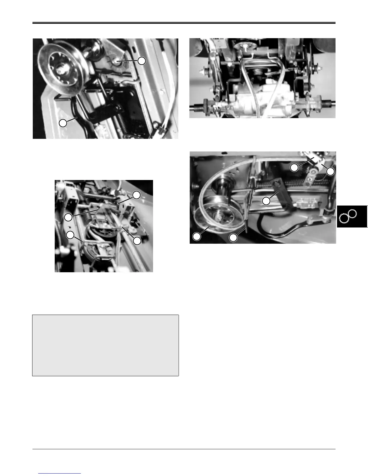
6. Depress and lock brake pedal (A) with park brake
lever.
7. Remove front idler belt guide and sheave (B).
8. Remove clutch bellcrank belt guide (C).
9. Remove adjustable idler belt guide (D).
10. Remove park lever (E).
11. Remove mower drive lever return spring (F)
?
CAUTION
Mower drive lever return spring is under tension
and located inside frame. Use pliers or spring
puller tool to remove spring. Protect your eyes
and face from the possibility of spring being
released at high speed.
B
A
E
D
C
F
12. Remove belt from transaxle drive sheave, and pull
through transaxle belt guide.
13. Pull belt from around engine drive sheave (G), and
past front belt guide (H). Pull belt under belt guide
and around steering arm (I).
14. Rotate mower drive lever to allow belt to pass
between lever (J) and switch (K).
15. Remove belt from clutch bellcrank and idler
sheave, and remove belt from mower.
TRACTION DRIVE BELT
INSPECTION
1. Examine belt to determine if it is worn, stretched,
cracked, frayed, or damaged beyond the point of
continued use.
2. Measure and compare removed belt to the
following:
New Belt Dimensions:
Length. . . . . . . . . . . . . . . 2660±8 mm (104.7±0.3 in.)
Minimum length . . . . . . . . . . . 2631 mm (103.6 in.)
Maximum length. . . . . . . . . . . 2710 mm (106.7 in.)
Top width . . . . . . . . . . . . . . . . . . 12.7 mm (0.500 in.)
Minimum top width . . . . . . . . . . . 11 mm (0.43 in.)
Depth . . . . . . . . . . . . . . . . . . . . . 7.874 mm (0.31 in.)
Minimum depth. . . . . . . . . . . . . . . . 7 mm (0.28 in.)
3. Replace belt if any of above dimensions are not
found.
H
G
I
K
J
www.servicemanualall.com



 To Next Page