GEAR POWER TRAIN THEORY OF OPERATION
5 - 12 2/12/97
BRAKE SYSTEM OPERATION
Function:
The brake system allows the operator to slow down,
stop, or lock the tractor into park position.
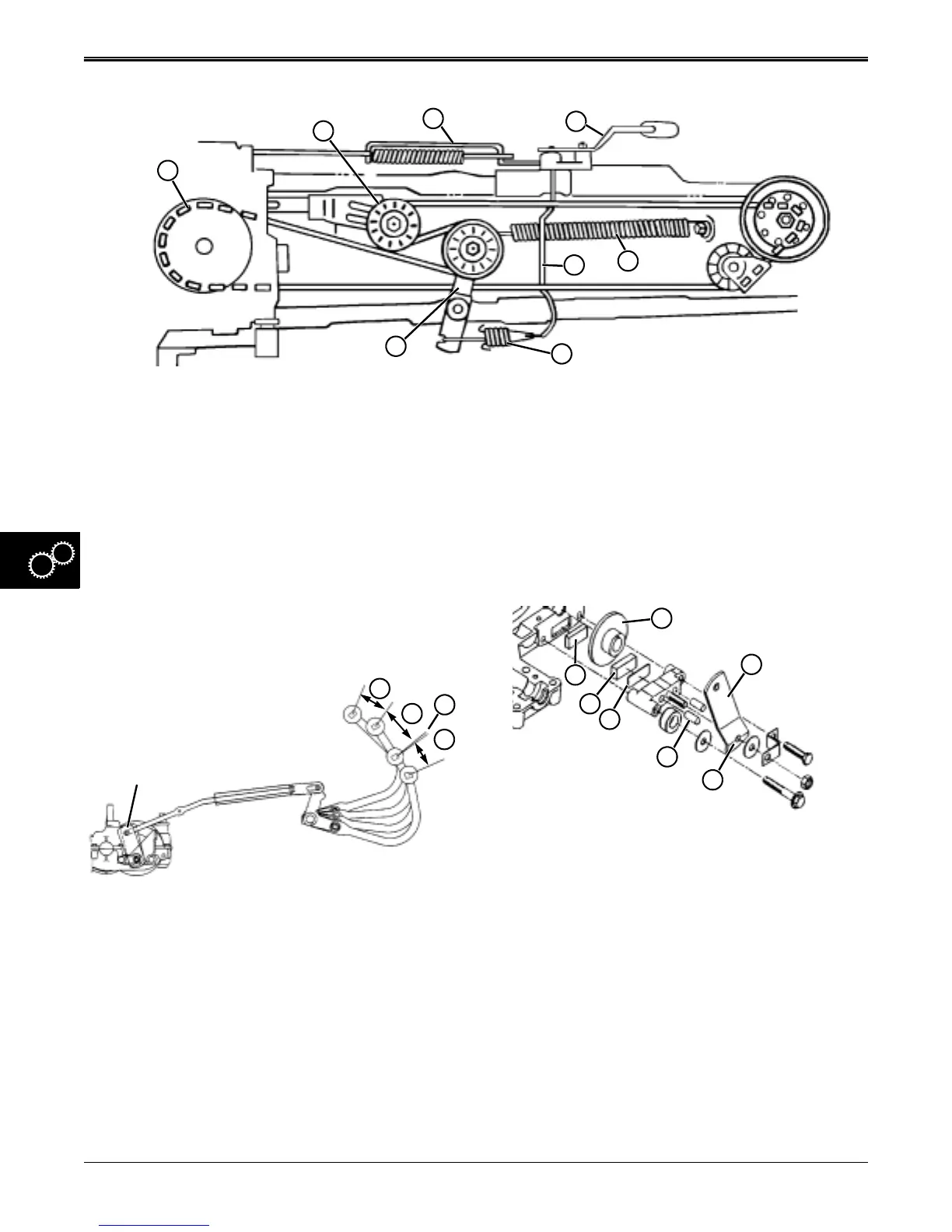
Theory of Operation:
NOTE: Clutch/brake pedal has approximately 127 mm
(5 in.) of travel, and operates as follows:
The first movement of the clutch/brake pedal (N) is
used for taking-up freeplay in the linkage and the
beginning of compressing the clutch actuating spring
assembly (C).
The next segment of pedal travel (O) is fully
compressing the clutch actuating spring assembly (C),
and pulling the clutch bellcrank and idler assembly (D)
fully rearward, overcoming the belt tensioning spring
(H) and fully disengaging the traction drive system.
As the pedal is released, belt tensioning spring (H)
pulls the clutch bellcrank and tensioning idler assembly
(D) forward into the belt, tensioning the belt and fully
engaging the traction drive system.
A. Clutch/Brake Pedal E. Adjustable Idler Assembly
B. Clutch Cross Shaft and Bellcrank F. Transaxle Drive (Input) Sheave
C. Clutch Actuating Spring Assembly G. Brake Rod Assembly
D. Clutch Bellcrank and Tensioning Idler Assembly H. Clutch Tensioning Spring
A
F
E
G
B
C
D
H
N
O
Q
P
Transaxle
Brake Assembly
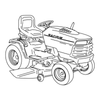
There is a small segment of pedal travel (P) that briefly
allows the tractor to free-wheel so the operator can
shift-on-the-go before the brake starts to engage. This
segment can be adjusted to allow more overlap
between clutch and brake functions, if desired.
The last segment of travel (Q) fully engages the brake
system. The brake lever (S), with the bottom cam
surface contour (I), pushes the two dowel pins (J)
against the striker plate (K). The striker plate forces the
thicker, outer friction puck (L) against the brake disc
(H). The two friction pucks (L and M) become
compressed against both sides of the brake disc (R).
The brake disc is keyed to the end of the intermediate
shifter/brake shaft (not shown). When the compression
force of the friction pucks is great enough to stop the
brake disc rotation, the transaxle and wheels stop
turning. This works in conjunction with the clutching
system.
With the clutch/brake pedal (A) fully depressed and the
traction drive system disengaged (fully clutched), the
park brake lever assembly (not shown) can be
engaged, locking the clutch/brake pedal linkage and
the brake disc in the park position.
S
J
I
K
L
M
R
www.servicemanualall.com