GEAR POWER TRAIN REPAIR
5 - 26 2/12/97
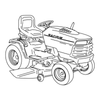
2. Turn upper case half so input shaft is facing up.
3. Remove woodruff key (J), E-ring (I), shim washer
(H), and input shaft (K).
IMPORTANT: DO NOT scratch or deform upper
case half bore when removing needle bearings.
4. Visually inspect condition of needle bearings, upper
bearing (J) and lower bearing (K). If needles are
discolored, spalled, scratched, missing, broken,
etc. replace bearings.
5. Measure inside diameters of each bearing:
K
H
I
J
J
K
Bearing Inside
Diameter . . . . . 15.89–15.92 mm (0.625–0.627 in.)
6. Replace both bearings by carefully pressing them
from case bore without damaging bore.
7. Pack area between bearing with Multi-Purpose EP
Grease.
8. Clean and inspect bore. If scratched or deformed,
replace upper case half.
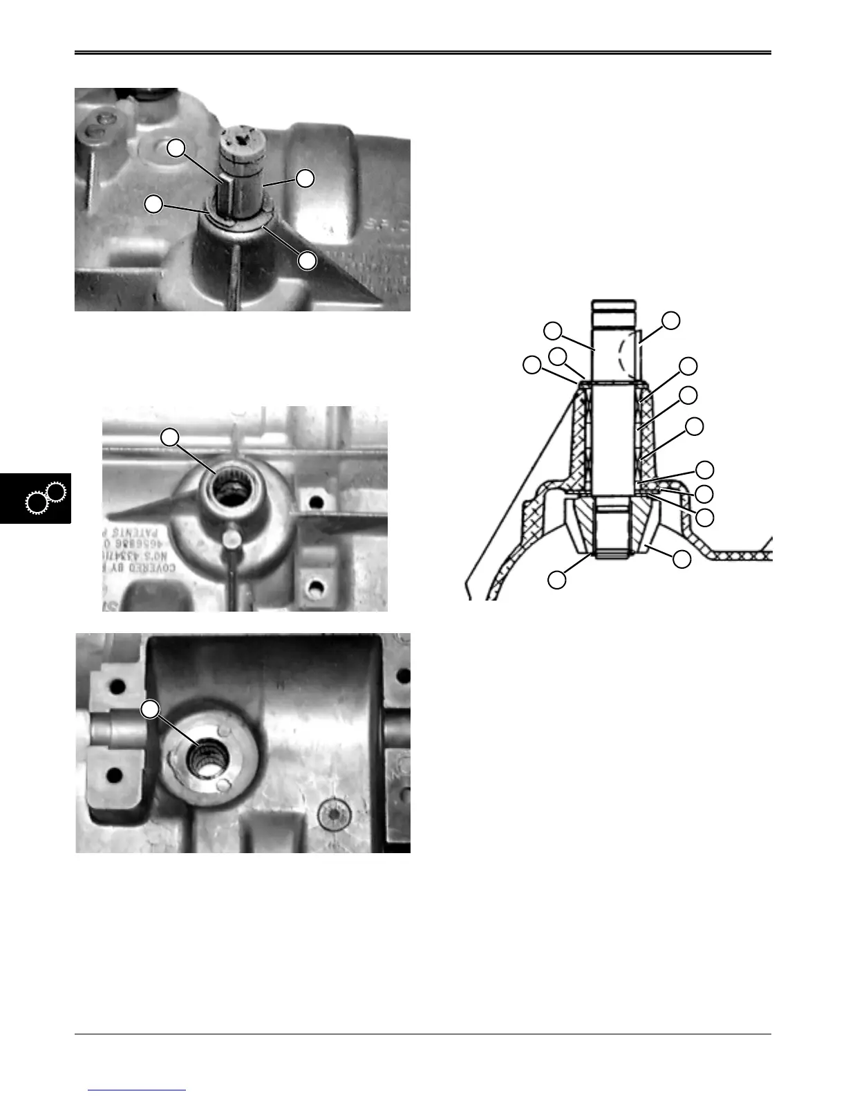
Assemble Input Shaft/Pinion Gear Assembly:
IMPORTANT: DO NOT scratch or deform upper
case half bore when installing needle bearings.
1. Pack needle bearings (A and B) with Multi-Purpose
EP Grease before installing.
2. Install lower needle bearing (B) with flat side of
bearing (with lettering) toward inside of case. Press
lower needle bearing in case bore with a maximum
recess of 0.76 mm (0.030 in.) (H) from case
surface.
3. Install upper needle bearing (A) with flat side of
bearing (with lettering) toward outside of case.
Press lower needle bearing flush with surface of
case bore. A maximum recess of 0.76 mm (0.030
in.) from case surface is also acceptable.
4. Pack cavities (G and H) with Multi-Purpose EP
grease before installing input shaft.
L
K
A
B
E
H
G
J
I
D
C
F
www.servicemanualall.com
 Loading...