GEAR POWER TRAIN REPAIR
5 - 28 2/12/97
Idler Gear Inspection:
1. Visually check overall condition of assembly,
including shaft and bushings, gears for wear,
pitting, broken teeth, etc.
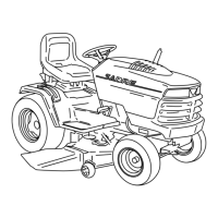
2. Use a feeler gauge to measure clearance (A)
between end surface of combination gear and side
surface of case half:
Clearance . . . . . . 0.33—0.63 mm (0.013 —0.025 in.),
3. If clearance is excessive worn and/or damaged
components need to be replaced.
Idler Gear Disassembly:
1. Lift idler gear assembly (A) from lower case half.
2. Clean components and disassemble.
A
A
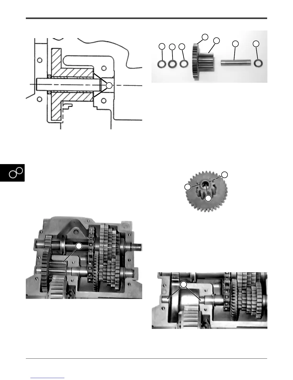
3. Separate and inspect idler components:
• Washers (B and D) should be 0.632 x 1.00 x 0.026
in., not scored nor discolored (burnt).
• Spacer (C) should be 0.630 x 1.00 x 0.169 in., not
scored nor discolored (burnt).
• Narrow combination gear (E) should have 35 good
teeth and wide combination gear (F) should have
12 good teeth, not scored nor discolored (burnt).
• Idler shaft (G) should be smooth and not scored,
pitted, nor discolored (burnt).
• Shim washer(s) (H) should be 0.632x1.00 and
range in thickness from 0.010 to 0.082 in.
• Inside bearing (I) and outside bearing (K), (which
are press fit), should not be scored nor discolored
(burnt);
NOTE: Replacement gear and needle bearings and a
new shaft are also recommended whenever
new gear is ordered.
4. Inspect lower and upper case halves idler shaft
bearing surfaces (L) for excessive scoring or wear.
Replace case halves as necessary.
B
C
D
E
F
G H
I
K
J
L
www.servicemanualall.com
 Loading...