REPAIR GEAR POWER TRAIN
2/12/97 5 - 31
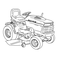
5. Install axle shafts so beveled gears (E) mesh with
differential internal shaft beveled gears.
6. Keep inward pressure on both axles as you install
differential assembly in lower case housing.
7. Measure air gap between shim washers (F) and
side of housing (H). If air gap meets specification
(see Inspect Differential/Axle Shafts Assembly), go
to next step. If air gap does not meet specification,
remove right axle shaft and add other shim washer
combinations until air gap in within specification.
8. Carefully install new axle shaft seals (G and I) and
seat them in their lower case housing grooves.
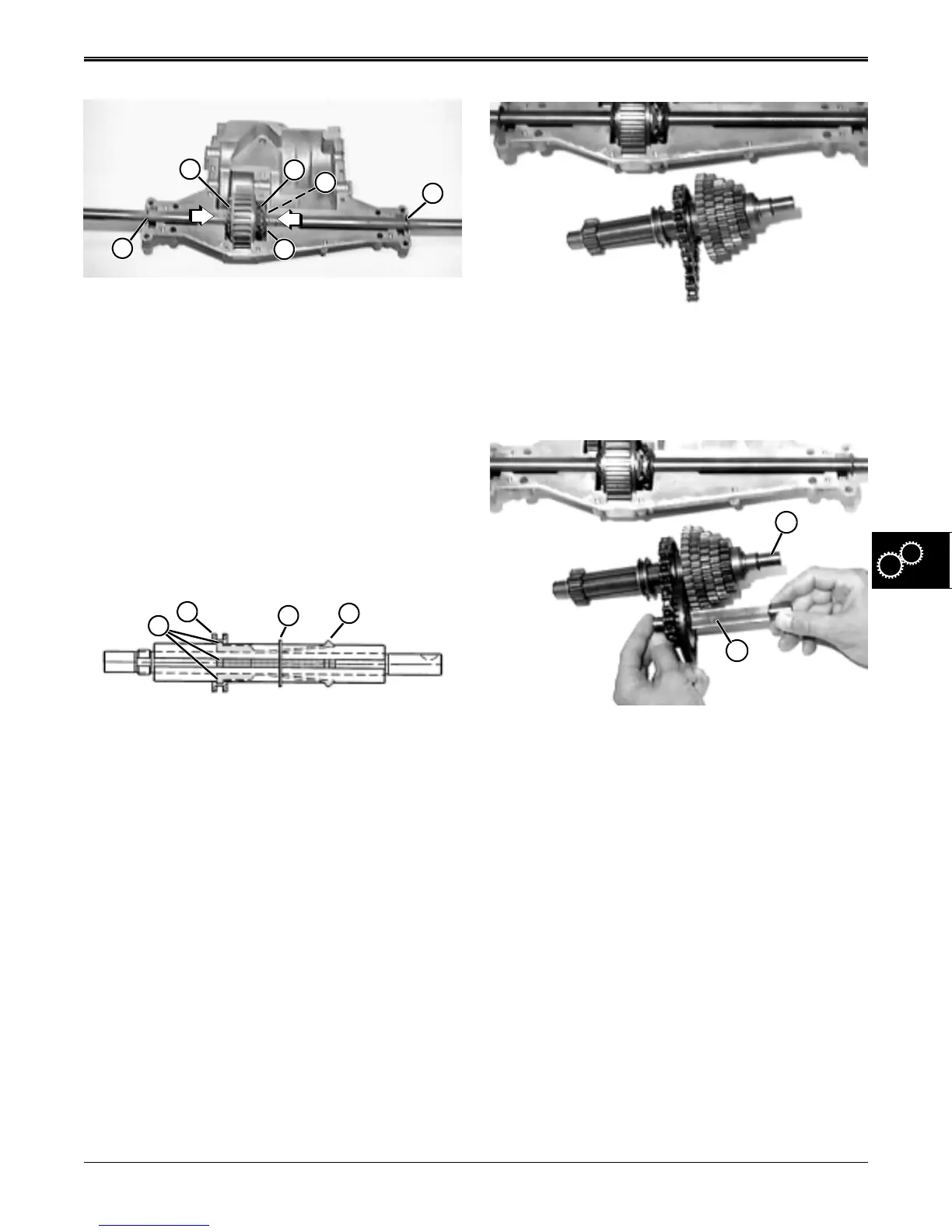
Assemble Drive/Intermediate Shaft Assemblies:
1. Install retaining ring (C) in intermediate shaft
groove.
2. Install four keys in grooves of intermediate shaft
and hold them so internal shift collar anchors (A)
will seat in internal groove of collar (B) as it is
installed on the shaft.
3. Slide shift collar and keys against retaining ring (C)
and compress locking ramps/lugs (D) to clear
retaining ring.
E
E
G
F
H
I
B
C
D
A
4. Install remaining intermediate shaft components in
their proper order and orientation (reference top
two rows of components in exploded view at the
beginning of this section).
5. Install drive shaft components one at a time from
left-to-right (reference bottom row of components
in photo M42335 at the bottom of this page). Long
flange of small sprocket (J) faces bevel drive gear.
6. Shim washer(s) (E) for intermediate shaft (F) are
found in Shim Kit.
7. Shim washer(s) (H) for drive shaft (I) are found in
Shim Kit.
8. Install new intermediate shaft seal (G) with open lip
facing inside.
F
I
www.servicemanualall.com
 Loading...