REPAIR GEAR POWER TRAIN
2/12/97 5 - 33
1. Pack upper case beveled pinion gear and lower
case housing assembly with 638 g (1.406 lbs) of
Multi-Purpose EP grease.
2. Apply Form-In-Place Gasket Silicone Sealant to
lower case.
3. BE SURE sealant DOES NOT contact any gear,
shaft, or bearing surfaces.
4. Align lower and upper case halves together, be
sure shaft seals are seated correctly and you may
have to turn input shaft (D) slightly to insure
beveled pinon gear meshes with beveled drive
gear.
5. Install 14 outside socket head screws (A) and two
center socket head screws (B) with new rubber
seals (C).
6. Tighten screws to 10 N•m (88 lb-in.).
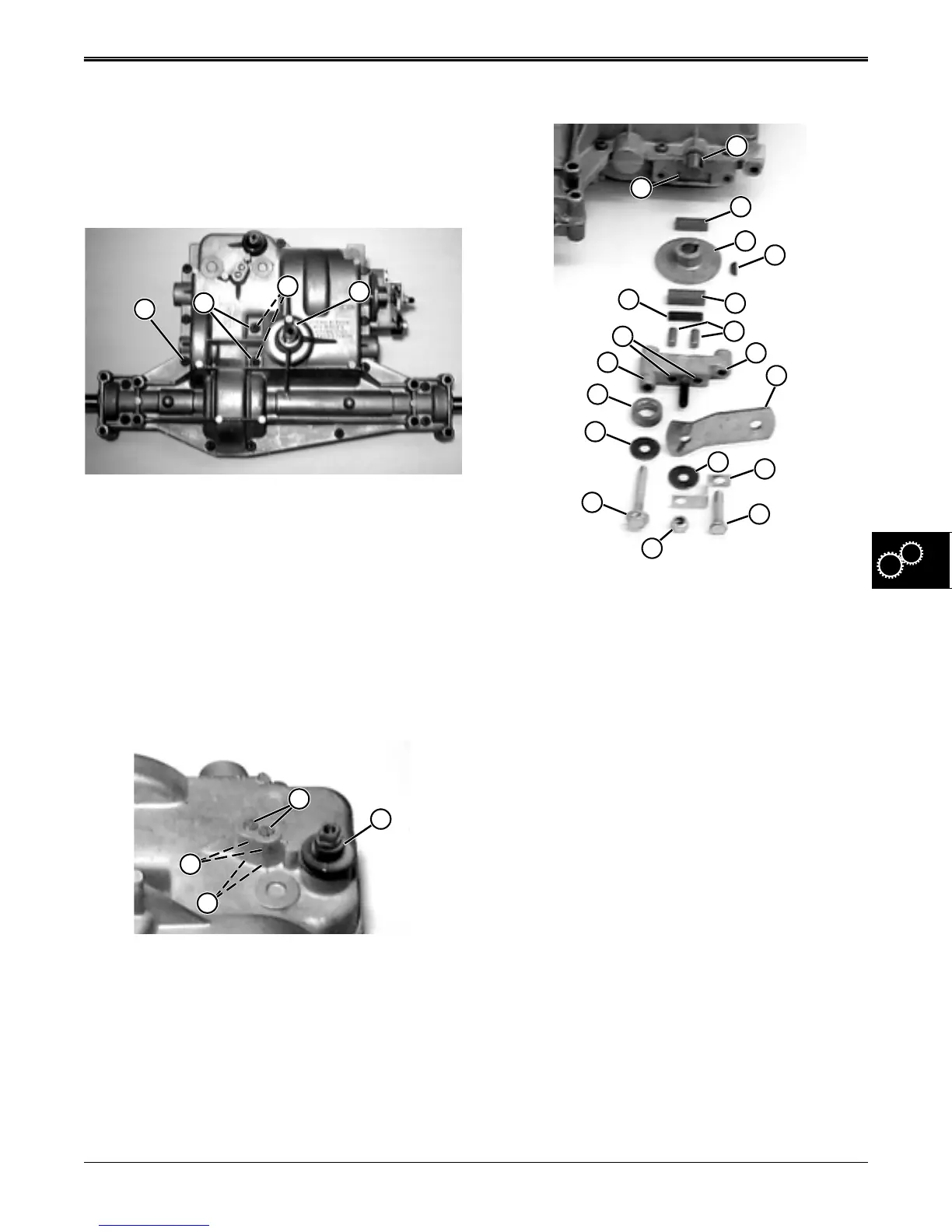
Install Shifter Detent Assembly:
IMPORTANT: DO NOT drop or lose detent balls.
1. Install shifter shaft rubber boot (B).
2. Coat detent balls (C) and springs (D) with
Never-Seez and install in case bores.
3. Install and tighten set screws (A) until they are flush
with top of mounting hole surface.
A
D
C
B
B
A
C
D
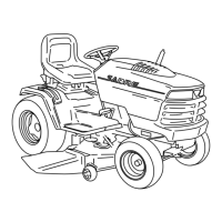
Install Brake Assembly:
1. Install woodruff key (D) into shaft keyway (A).
2. Install thinner friction puck (B) in lower case puck
recess (S).
3. Install brake disc (C) with hub outward.
4. Install spacer (O) over left lip (P) of mounting
bracket.
5. Install long cap screw (M) and washer (N) in left
mounting bracket hole.
6. Install brake lever (H), washer (I), bent bracket (J),
and lock nut (L) on mounting bracket center stud.
7. Install short cap screw (K) in right mounting bracket
hole (G).
8. Install dowel pins (F) inside two center mounting
bracket holes (Q).
9. Install striker plate (R) and thick friction puck (E) in
backside recess of mounting bracket.
B
C
E
A
S
D
R
G
H
P
O
N
M
J
I
K
L
F
Q
www.servicemanualall.com
 Loading...