66 VG5 Installation & Quick-Start Manual
EF3
External Fault 3
External fault at
terminal 3
Fault occurred in the external control
circuit.
Check the condition of the
input terminal. If the LED
lights when terminal is not
connected, then the inverter
requires repair.
A
EF4
External Fault 4
External fault at
terminal 4
Fault occurred in the external control
circuit.
Check the condition of the
input terminal. If the LED
lights when terminal is not
connected, then the inverter
requires repair.
B
EF5
External Fault 5
External fault at
terminal 5
EF6
External Fault 6
External fault at
terminal 6
EF7
External Fault 7
External fault at
terminal 7
EF8
External Fault 8
External fault at
terminal 8
OPE01
kVA Selection
kVA setting error
(OPE01)
Inverter kVA setting error.
Check and set the parameter
data (O2-04).
C
OPE02
Limit
Parameter setting
range error (OPE02)
Parameter data is out of range.
Check the parameter data
settings.
C
OPE03
Terminal
Multi-function input
setting error (OPE03)
·Multi-function input settings in H1-01
to H1-06 are not in ascending order.
·Or, set values other than “F” are over-
lapping.
Check the function selection. C
OPE10
V/f
V/f data setting error
(E1-04 to E1-10)
V/f data is set such that the following
equation is not satisfied:
E1-04 E1-06 > E1-07 E1-09
Check the parameter data
settings.
C
OPE11
FC/ On-Dly
Parameter setting error
When one of the following setting
errors occurs:
·Carrier frequency upper limit
(C6-01) > 5kHz, and Carrier
frequency lower limit (C6-02)
5kHz
·Carrier frequency proportional gain
(C6-03) > 6 and (C6-01) < (C6-02)
Check the parameter data
settings.
C
ERR
EEPROM R/W Err
EEPROM writing fault
(ERR)
EEPROM internal data did not match
when initializing the parameter.
Replace the control board. B
CALL
Serial Com Call
SI-B transmission error
Control data was not received correctly
when power supply was turned ON.
Check transmission devices
and transmission signals.
C
CE
Memobus Com Err
Transmission error
Control data was not received correctly
when power supply was turned ON.
Check transmission devices
and transmission signals.
A
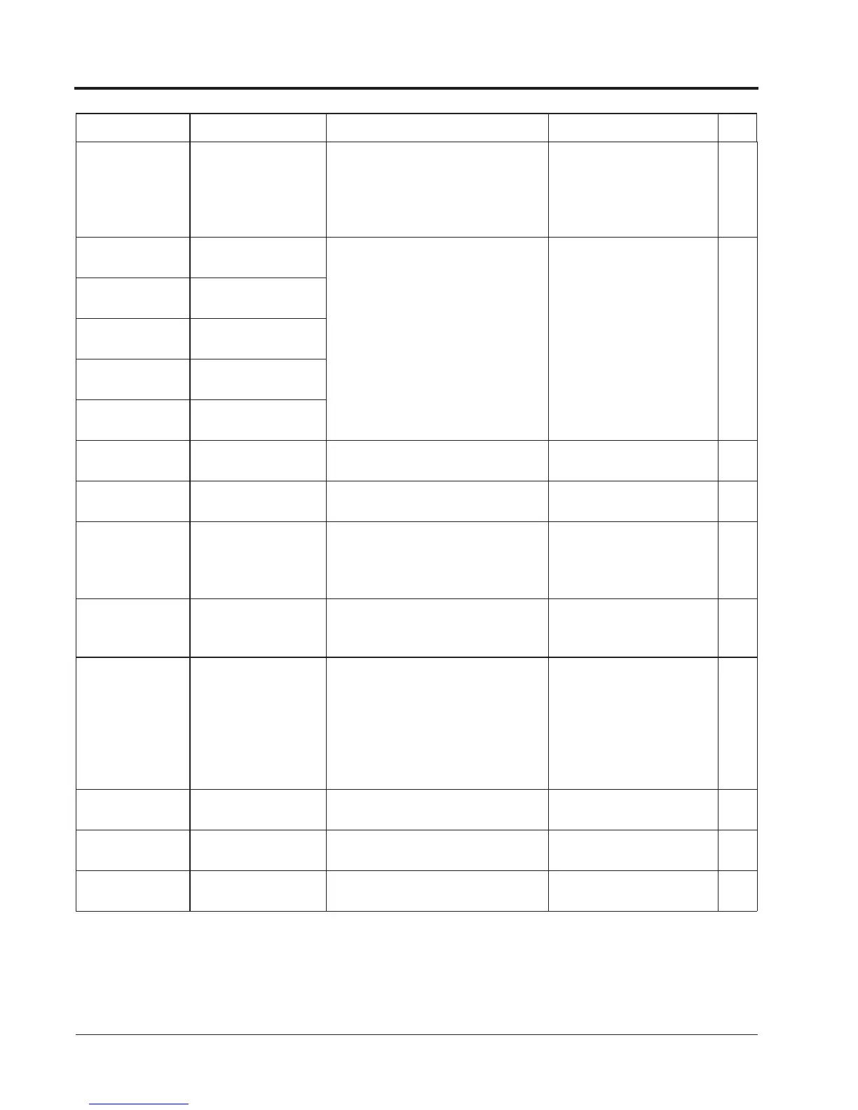
Fault Display Name Description Corrective Action Class
Chapter 4 - Diagnostics
Alarm & Fault Displays