VG5 Installation & Quick-Start Manual 73
Monitor
U1-25
D1-16H Input Status*
(DI-16 Reference)
—
Displays input value according to F3-01 setting.
For example:
When lower 8 bit is ON,
Binary selection: 256, BCD selection: 99
— A A A A
U1-26
Output Voltage Refer-
ence Vq
(Voltage Ref (Vq))
0.1V —
10V/200V or
400V
x x A A
U1-27
Output Voltage
Reference Vd
(Voltage Ref (Vd))
0.1V —
10V/200V or
400V
x x A A
U1-28
Software No. at CPU
Side*
(CPU ID)
— — — A A A A
U1-32
ACR (q) Output
(ACR (q) Output)
0.1% — — x x A A
U1-33
ACR (d) Output
(ACR (d) Output)
0.1% — — x x A A
U1-34
OPE Detection
Parameter*
(OPE Detected)
— — — A A A A
U1-35
No. of O Servo Moving
Pulses
(Zero Servo Pulse)
1 — — x x x A
U1-36
<1110>
PID Deviation
(PID Input)
0.01%
PID reference + PID reference bias – PID feedback
capacity
10V/Max.
Output Fre-
quency
A A A A
U1-37
<1110>
PID Output Capacity
(PID Output)
0.01% PID output capacity
10V/Max.
Output Fre-
quency
A A A A
U1-38
<1110>
PID Reference
(PID Setpoint)
0.01% PID reference + PID reference bias
10V/Max.
Output Fre-
quency
A A A A
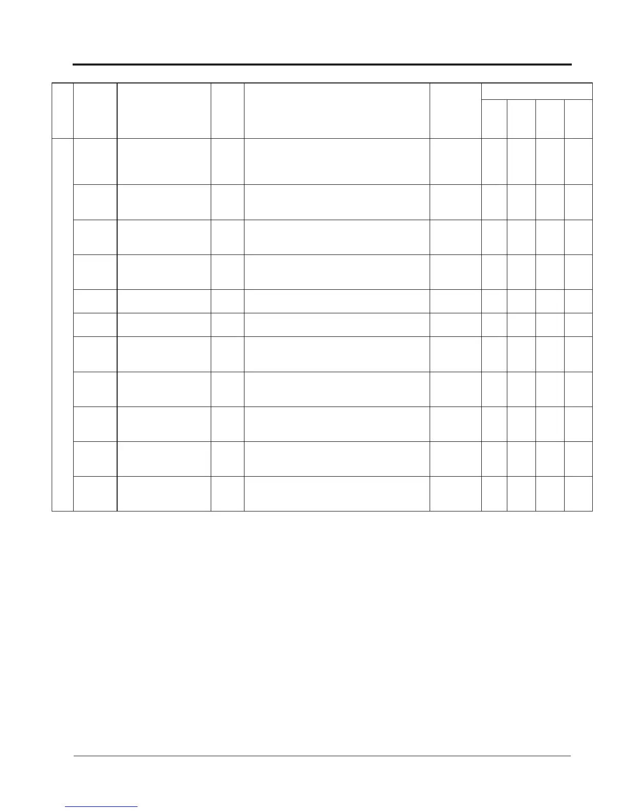
Function
Parameter
No.
Name
(Digital Operator Display)
Min.
Unit
Description
Analog
Monitor
Output Level
Parameter Access Level
V/f
V/f w/
PG
Vector
w/o
PG
Vector
w/ PG
Appendix
VG5 Parameter List U Monitor
* Cannot be changed by U1-04