VM1000B
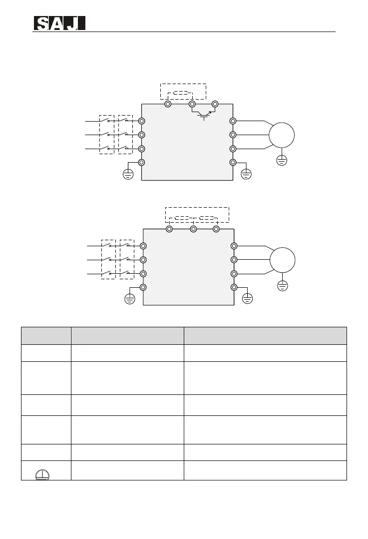
2.3 Main circuit connection
M
R/L
S
T/N
+
PB
-
U
V
W
PE
Braking resistor
MCCB MC
Power Input
terminal
L1
L2
L3
External component
Out terminal
Main circuit
PE
0.75kW-22kW
Figure 2-3-1 0.75kW-22kW main circuit wiring diagram
M
R
S
T
+
P
-
U
V
W
PE
DC reactor
MCCB MC
L1
L2
L3
Out terminal
PE
Braking resistor
Power Input
terminal
30kW-110kW
Main circuit
External component
Figure 2-3-2 30kW-110kW main circuit wiring diagram
Power supply input terminals
Connect to the AC power supply
Positive and negative terminals of
DC bus
Common DC busbar input terminal
Connect the external braking unit to the AC drive
of 30 kW and above Power Range
Brake resistance
connecting
terminal.
Connect to the braking resistor for the AC drive of 22
kW and below Power Range
Connecting terminals of
external reactor
Connect to an external reactor.
AC drive output terminals
Connect the three-phase motor.
Table 2-3-1 Main circuit terminals and function