EasyManua.ls Logo

SAJ VM1000 User Manual

SAJ VM1000
148 pages
To Next Page IconTo Next Page
Page #1 background imageLoading...
Page #1 background image
VM1000 Series
‐0‐
资料代码:
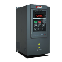
VM1000 AC Drive
User Manual
Version Code :VM1000-E2016-04-1MB

Questions and Answers:

SAJ VM1000 Specifications

General IconGeneral
Rated AC Output Power1000 W
Protection DegreeIP65
Rated AC Voltage230V
CommunicationRS485, Wi-Fi
Operating Temperature Range-25°C to +60°C
Output Voltage230V AC
Frequency50 Hz / 60 Hz
Cooling MethodNatural cooling
Operating Temperature-25°C to +60°C
Storage Temperature-40°C to +70°C

Summary

Preface

Precautions

Definition of Warning Signs

Explains DANGER, WARNING, and NOTE symbols used in the manual.

Product Warning Signs

Describes warning indicators present on the product itself.

Signs, Abbreviation and Brandmark Statement

Signs

Defines common technical symbols like PE, GND, SHIELD.

Name Abbreviation

Lists common abbreviations for VFD and related terms.

Trademark

Lists product trademarks and their owners.

Chapter 1 Product Information

Production Introduction

Overview of VM1000 AC drive, its applications, and power range.

Technical Specification Table

Details VFD specifications like frequency, torque, and overload capacity.

Product Nameplate

Explains the information provided on the product's nameplate.

Model Description

Details the meaning of each component of the VFD model number.

Dimension of AC Drive

Provides installation dimensions for various VM1000 models.

Dimension of Keyboard

Shows dimensions for the operation keyboard and its mounting hole.

Specification of Selecting Products

Lists VFD models with corresponding power, current, and motor specifications.

Maintenance

Covers routine maintenance, periodic inspection, and component replacement procedures.

Chapter 2 Installation

Mechanical Installation

Details VM1000 structure, removal steps, and environmental requirements.

Electrical Wiring

Covers electrical operation conditions, safety precautions, and wiring diagrams.

Electro Magnetic Compatibility

Discusses EMI/EMC precautions and solutions for interference issues.

Chapter 3 Panel Display and Operation

Introduction of Operation&Display Interface

Explains the VFD's operation panel layout, indicators, and display.

Keys and Functions of Operation Panel

Details the function of each key on the VFD's operation panel.

Function Code Viewing, Modification Instruction

Guides on navigating and modifying function codes and parameters.

Viewing Methods of Status Parameters

Explains how to view various operational status parameters displayed by the VFD.

Password Setting

Describes how to set and manage user passwords for parameter protection.

Chapter 4 Quick Debugging Guide

Preparation and Examination Before Commissioning Operation

Lists checks for electric and mechanic conditions before initial operation.

Panel Operation

Covers typical panel operations like start/stop and parameter setting.

Start/Stop Control of Terminal Forward Rotation

Guides on wiring and parameter settings for terminal start/stop control.

Common Control Guideline

Explains multi-step speed and PID control applications and parameters.

Auto-tuning of Motor Parameters

Details the procedure for motor auto-tuning in vector control mode for optimal performance.

Faults Query and Reset Step

Essential steps for viewing fault codes and resetting the VFD.

Parameters Restore as Factory Value

Explains how to restore VFD parameters to their factory default settings.

Chapter 5 Function Code Datasheet

F0 Group: Basic Parameters

Lists and describes basic VFD parameters like control mode and command source.

F1 Group: Start and Stop Parameters

Details parameters related to VFD start, stop, and braking functions.

F2 Group: Motor Parameters

Lists parameters for configuring motor characteristics for optimal performance.

F3 Group: Vector Control Parameters

Describes parameters specific to vector control mode operation.

F4 Group: V/F Control Parameters

Details parameters for V/F control mode, including curve settings.

F5 Group: Input Terminals Parameters

Configuration of digital and analog input terminals for external control signals.

F6 Group: Output Terminals Parameters

Configuration of digital and analog output terminals for status feedback.

F7 Group: Keypad & Display Interface Parameters

Parameters related to the operation panel, display, and keypad functions.

F8 Group: Auxiliary Function Parameters

Parameters for auxiliary functions like jump frequency and simple PLC.

F9 Group: PID parameters

Parameters for configuring the PID control loop for closed-loop systems.

FA Group: Protection Parameters and Fault Record

Configuration of various protection functions and fault management.

FB Group: Swing frequency, length control and counter control

Parameters for swing frequency, length, and counter functions.

FC Group: RS485 Communication Parameters

Settings for RS485 communication protocol and parameters.

FD Group: Multi-step Speed and Simple PLC Parameters

Parameters for multi-step speed and simple PLC operation.

FE Group: Parameter Management

Settings for user password and fault record display.

Chapter 6 VM1000 Communication Application

The Content of Protocol

Defines the serial communication protocol content and format for data transmission.

Application

Describes how VFD connects to PC/PLC networks via RS485 for control.

Bus Structure

Details RS485 interface, transmission mode, and topology for communication.

Protocol Instruction

Explains the master-slave ModBus communication protocol used by the VFD.

Communication Frame Description

Describes the RTU mode frame format and CRC checking for data integrity.

Register Address

Lists addresses for stop/running parameters essential for programmatic access.

Chapter 7 Faults and Solutions

Fault Code Table

Lists fault codes and provides troubleshooting flowcharts for common faults.

Troubleshooting and Solution

Direct problem-solving guide with common faults, reasons, and solutions.

Appendix A - Selection of External Electrical Components

VM1000 External Electrical Connection Diagram

Illustrates the external electrical connection diagram for the VM1000.

Selection Guide of Braking Components

Provides guidance on selecting braking resistors based on power and resistance requirements.

Selection of Air Switch, Contactor or Cable

Offers recommendations for selecting electrical components like switches, contactors, and cables.

Appendix B - Manual Revision Record

Related product manuals