VM1000B
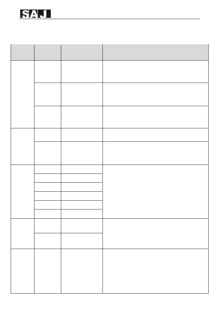
Control terminal instruction
Provide +10V power supply to external unit.
Generally, it provides power supply to external potentiometer with
resistance range of 1-5 kΩ.
Maximum output current: 20 mA
Provide +24V power supply to external unit.
Generally, it provides power supply to DI/DO terminals and
external sensors.
External power input
terminal
Connect to +24V by default.
When DI1-DI6 need to be driven by extemal signal, OP needs to
be connected to external power supply and be disconnected from
+24V.
1. Input voltage range: 0-10V
2. Input resistance: 22 kΩ
1. Input range: 0-10V/4-20mA, decided by jumper J8 on the
control board.
2. Input resistance: 22 kΩ(voltage input), 500Ω(current input)
1. Optical coupling isolation, compatible with dual polarity input
2. Input resistance: 3kΩ
3. Voltage range for level input: 9V -30V
AO1: Voltage or current output is decided by jumper J5.
Output voltage range: 0-10V
Output current range: 0-20mA
AO2: Output voltage range: 0-10V
Digital output/high-
speed pulse output
Output voltage range: 0V -24V
Output current range: 0mA - 50mA
Note that CME and COM are internally insulated, but they are
shorted by jumper externally. If you want to drive FM by external
power supply, Please remove the jumper.