095
0: digital setting
Set the target voltage value by function
code F5.15.
F5.13
voltage setting channel
0~2 0
Fig. F5-7 Voltage Control Mode 2
2: VF fully separated mode, voltage open-loop
output
In this mode, output frequency and voltage
of VFD are completely independent.
Frequency changes according to set acc/
dec time, voltage is adjust to target value
according to rise/fall time dened by F5.19,
F5.20, as showed in gure F5-7. This control
mode is mainly applied in designing of
some variable-frequency power source.
3 : VF fully separated mode, voltage closed-
loop output
The only difference of this mode from
mode 2 is that it introduced voltage closed-
loop. Through PI adjustment of deviation
of feedback voltage compared with set
voltage, a steadier voltage can be acquired.
This method can compensate target voltage
deviation caused by load change, so as to
acquire a higher precision of voltage control
and a faster response.
6
' '
4.2 Detailed Function Description
Notice:
Analog feedback channel voltage has a corresponding
relation F6.06 ~ F6.11 with actual voltage, and the
relation is only determined by voltage transducer (PT),
the computational method is as follows:
Hypothetically U*=120%*Ue=456V(AI1)
PT ratio=50 (input AC 0-500V, output DC 0-10A)
When output reaching the target voltage 456V, the
feedback voltage of PT output is
456/50V=9.12V
AI1 upper limit input is 10V, input voltage is 500V, the
ratio to rated voltage value is
500/380=132%
So F6.09 (AI2 input upper limit voltage) can be set as
10.00V, F6.10 (AI2 upper limit corresponding setting)
can be set at 132%.
This control mode is widely applied in areas
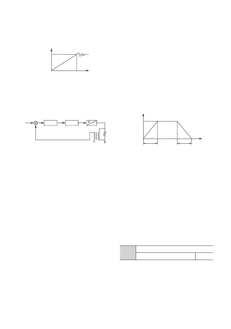
like EPS power source. The control principle is
as showed in the following wireframe gure.
Fig. F5-6 EPS Control Principle
U*——setting value of P5.13 channel
U1——analog feedback voltage (PT)
PT——electrical quantity transducer
6
*OWFSUFS
-$'JMUFS
:
Fig. F5-5 Voltage Control Mode 1
6