119
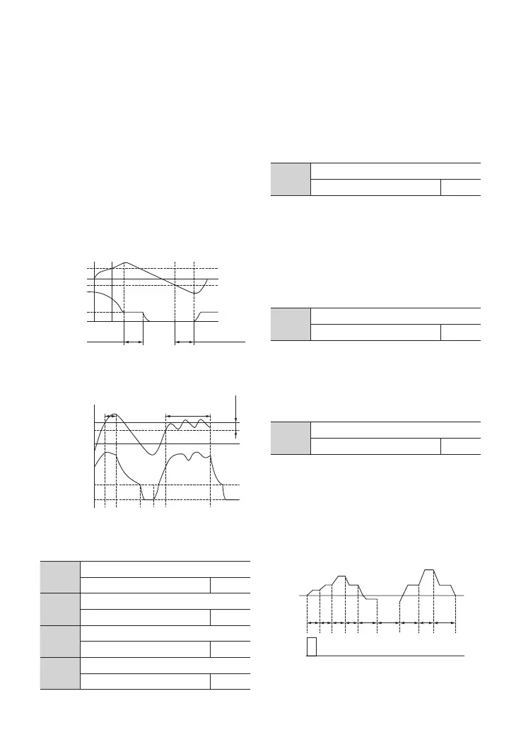
Fig. F8-5 the First Sleep Mode
1*%4FUUJOH
8BLFVQ
8BLFVQ
8BLFVQ
0VUQVU'SFR
-PXFS-JNJU
PG'SFR
;FSP'SFR
4MFFQ
%FUFDUJPO5JNF
4MFFQ
Fig. F8-6 the Second Sleep Mode
1*%4FUUJOH
1*%4MFFQ%FMBZ 1*%4MFFQ%FMBZ
4FU%FWJBUJP
4MFFQ
8BLFVQ
0VUQVU'SFR
-PXFS-JNJU
PG'SFR
;FSP'SFR
4.2 Detailed Function Description
F8.19 ~ F8.20 are delay time of adding and
reducing pump in constant pressure water
supply system, see function NO.31 and NO.32
in F7.18 ~ F7.21.
F8.17
delay time of sleep
0.0 ~ 6000.0S 100.0
F8.18
delay time of wake-up
0.0 ~ 6000.0S 5.0
F8.19
delay time of adding pump
0.0 ~ 3600.0S 10.0
F8.20
delay time of reducing pump
0.0 ~ 3600.0S 10.0
Fig. F9-1 Stop after a Single PLC Cycle
0: stop after a single cycle
As Fig.F9-1 shows, the driver stops after
a single cycle. It will start given another
command. If operation time is 0 in some
segment, the driver will skip to another
segment.
F9.00
PLC running mode
0~3 0
F9 Programmable Operation Parameter
G
G
G
E
E
G
B
B E
G G
B E
G
B
5 5 5 5 5 5_5 5 5 5
B
B
B
F8.34
Sleep frequency
0.00HZ ~【F0.16】 0.00
F8.21
water supply enabling
0~2 0
0: invalid
1: PFC enabled
2: SPFC enabled
Note: Function code F8.21 ~ F8.24 needs
hardware support
operation) after delay time dened by F8.17.
F8.16 defines the feedback limit when the
driver is entering operating state from sleep
mode. When PID selects positive characteristic
and the actual feedback is smaller than
this set value (or when PID selects negative
characteristic and the actual feedback is
larger than this set value), the driver will start
to operate from sleep mode after delay time
dened by F8.18.