120
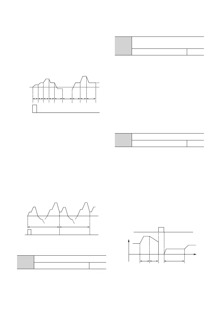
Fig.F9-3 PLC Continuous Cycle
0: auto
1: manual input via multi-functional terminal
F9.01
Input mode of PLC running
0~1 0
F9.02
PLC running state saving after
powero
0~1 0
0: not save
The PLC state will not be saved when
powero, and the driver will start from the
rst stage after powerup.
1: save
The PLC state including the stage, frequency
and run time will be saved when powero.
After powerup and receiving run command,
the driver will run at the preset frequency
of the stage for the remaining time of the
stage.
Fig.F9-2 Maintain Last Stage
after Single Cycle
1: maintain value of the last stage after single
cycle
As Fig.F9-2 shows, the driver holds the
frequency and direction of the last stage
after single cycle.
2: continuous cycle of limited times
The driver runs with cycle times set by
F9.04, and stops after reaching of cycle
times. If F9.04=0, the driver won't run.
3: continuous cycle
The driver continues running cycle after
cycle until stop command is received, as
showed in the following gure.
G
G
G
E
E
G
B
B
G G
B E
G
B
5 5 5 5 5 5_5 5 5 5
B
B
B
UIF'JSTU$ZDMF UIF4FDPOE$ZDMF
B
G
G
B
B
B
B E
E
B
B
B E
B
G
G
G
G
G
G
G
E
4.2 Detailed Function Description
0: start from the rst stage
The driver restarts from the first stage of
PLC after interrupts, such as stop conunand,
fault or powero.
1: continue from the stage where the driver
stops
When the driver stops caused by stop
command, fault or poweroff, it can record
the time that it has undergone in the current
stage. After restart, it will run at the preset
frequency of the stage for the remaining
time of the stage, as Fig. F9-4 shows.
F9.03
PLC restart mode
0~2 0
Fig. F9-4 PLC Start Mode 1
B
E
B
B
G
G
4UPQQJOH4JHOBM
B"DDUJNFPGTUBHF
B"DDUJNFPGTUBHF
B"DDUJNFPGTUBHF
G'SFRPGTUBHF
G'SFRPGTUBHF
G'SFRPGTUBHF
4UBHF
0QFSBUJOH
5JNFPG
4UBHF
3FNBJOJOH
5JNFPG4UBHF
G