ENGLISH
9
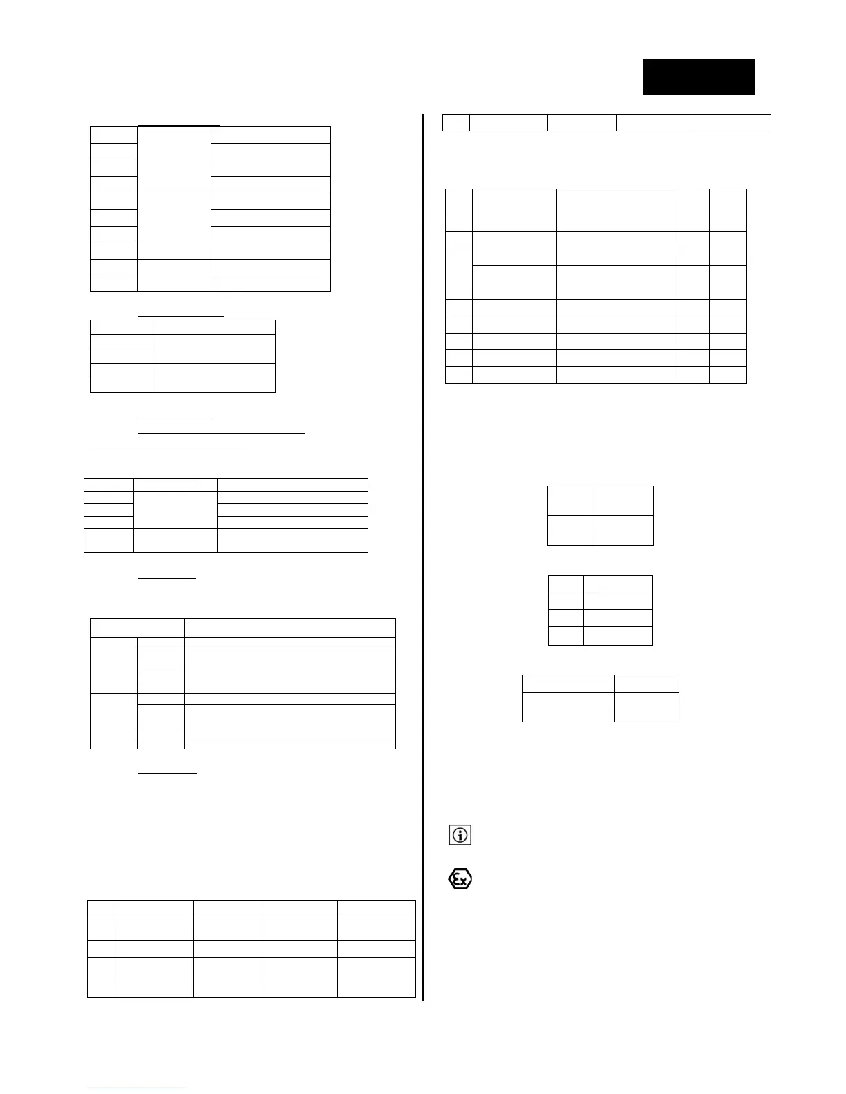
5:(21) Completepumpset
11
Closecoupled
Standard
12 Withportableframe
13 Ontrolley
14 Ontrailer
21
Biblock
Standard
22
Onbaseframe
23
Ontrolley
24
Ontrailer
31
With bearing
assembly
Onbaseframe
35
Bareshaft
6:(T ) Motorpowersupply
T Three‐phase
M Singlephase
D Diesel
E Gasoline
N Withoutmotor
7:(11) Installedpower
(inkW)
8:(2) Numb erofpoleforanelectricmotor
Numberofcylindersforan engin e
9:(K) Motoroptions
Code Optionfor Description
[empty]
Electricmotor
Nooption
K CTPsensor
S ON/OFFswitch
A,B,C,E,
F,G,H,N
Engine Variantsofpumpsetswithengine
10:(3B) ATEXmarking
ThissectionofthepumpcodeisindicatedonlyifpumpisATEXcertified.
Marking is engraved on pump nameplate. Correspondence between
codeandATEXdescriptionisindicatedinthefollowingtable:
Code RelatedATEXmarking
2
A ZONE1‐CAT.2‐II2GT(x)
B ZONE1‐CAT.2‐II2G‐ExdIIBT4
C ZONE1‐CAT.2‐II2G‐ExdIICT4
D ZONE1‐CAT.2‐II2G‐ExdeIIBT4
E ZONE1‐CAT.2‐II2G‐ExdeIICT4
3
A ZONE2‐CAT.3‐II3GT(x)
B ZONE2‐CAT.3‐II3G‐ExdIIBT4
C ZONE2‐CAT.3‐II3G‐ExdIICT4
D ZONE2‐CAT.3‐II3G‐ExdeIIBT4
E ZONE2‐CAT.3‐II3G‐ExdeIICT4
11:(‐X) Specialdesign
Themarking “x” correspondstoa specificdesignandis indicatedatthe
endoftheconstructioncode.Thedetaileddataregardingthepumpare
availableintheacknowledgmentoforder.
5.2 TECHNICALCHARACTERISTICS
5.2.1 MATERIALS
Materials
The following table indicates pump parts materials according to pump
materialcode(seechapter«5.1Typekey).
Code Pumpcasing Impeller Shaft/sleeve Wearplate
F Castiron Castiron StainlessSteel
Castironorcarbon
steel
E Castiron SS316 StainlessSteel StainlessSteel
Z
Castiron+
zincanode
Bronze or stainless
steel
StainlessSteel
Bronze or stainless
steel
B Bronze Bronze StainlessSteel Bronze
X SS316 SS316 SS316 StainlessSteel
Sealing
The following table indicates mechanical seal and gaskets materials
accordingtopumpmaterialcode(seechapter«5.1Typekey).
Code Pumpsize Mechanicalseal Gaskets NRV
A All SiC/Ceram/FPM NBR NBR
B All SiC/Ceram/FPM FPM FPM
C
S40to42 WC/SiC/PTFE PTFE PTFE
S45to161 WC/SiC/PTFE(bellows) PTFE PTFE*
S170toS230 WC/SiC/PTFE PTFE No
F All Carbon/SiC/FPM NBR NBR
G All Carbon/SiC/FPM FPM FPM
H S45to161 Carbon/SiC/PTFE PTFE PTFE*
J All Carbon/SiC/EPDM EPDM EPDM
K All WC/WC/NBR NBR NBR
*Availableuptosize2’’
5.2.2 PERFORMANCEAND OPERATING LIMITS
5.2.2. 1 TEMPERATURE
Maximumworkingtemperaturewillbethemostrestrictivetemperature
selectedinthetableshereafter:
Temperaturerangeaccordingcasingmaterial:
Cast
iron
‐30to
+140°C
Stainless
steel
‐40to
+140°C
Temperaturerangeaccordinggaskets:
NBR‐20to+120°C
FPM‐20to+140°C
PTFE‐40to+140°C
EPDM ‐40to+120°C
Temperaturerangeaccordingmotorassembly:
Closecoupled‐40to+75°C
Biblockoron
baseframe
‐40to
+140°C
5.2.2. 2 MAXIMU MWORKINGPRESSURE
Allpumps:6bar.
5.2.2. 3 OPERATINGRANGE &MINIMUMFLOW
S pumps are designed so that they can be used on the complete
hydrauliccurverange.
Runing the pump at duty points on extreme points of the curve
willdrivetoafasterwearofso
mepumpparts.
WhenthepumpisusedinanATEXzoneitisnecessarytomeasure
thedutypointandcheckthattemperatureincreasecorresponding
to each working condition is acceptable regarding selected surface
temperature.
The formula below gives the correspondence between surface
temperature/fluidtemperatureandpumpeffi
ciency:
T
o
=T
f
+
v
v
=[(g.H)/(c.)]*(1‐)



 To Next Page