Installation
Terminal Description Backplate
Common Terminal
1 (COM)
2 (NC)
Switched Live OFF
3 (NO)
Switched Live ON
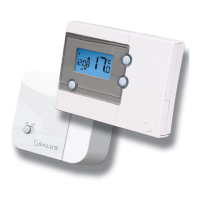
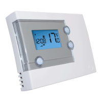
Unscrew the backplate of the thermostat in order to do the wiring connections. You can set your RT510 directly
on the wall or by using wall boxes. The wall boxes must have minimum 4 holes, a rear and bottom cable entry
and has a standard diameter of 60mm with a depth between 41mm-46mm.
Note: Make the connection by following the below table and electrical diagram.
1 2 3
Electrical diagram
(COM) (NC) (NO)
Features
• 5/2 days or 24h programming flexibility
• Built-in start up programming for quick installation
• Volt free contacts
• Frost protection
• Large, easy to read LCD with blue backlight
• Burner on symbol
• User friendly
• Stylish casing
• Holiday Mode
• Boost Function
RT510 Installation Manual 05