3-1
Existing Wired Thermostat Removal
Use the following procedure to review and record the wiring conguration
before disconnecting an existing wired thermostat.
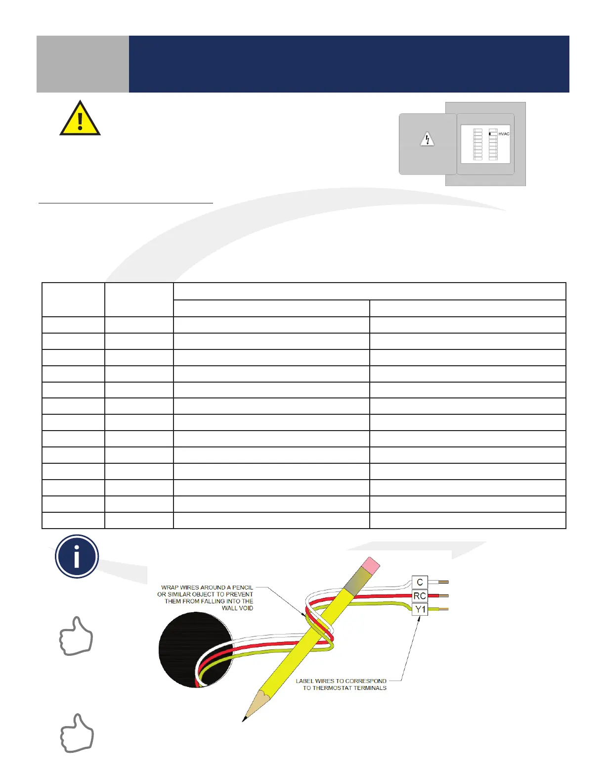
Before beginning the installation procedure, turn
o power to the fan coil system.
Section 3
SC102ZB/ST103ZB Installation and Operation Manual
SC102ZB Fan Coil Controller Installation
If replacing an existing wired thermostat, review and record the wiring conguration of the existing
thermostat:
• Remove existing thermostat from the wall to expose the wiring terminals
• Take a photograph or note the wire colors and connections (see Table 3.1 below)
• Attach wire labels to each of the wires
Table 3.1: Wire Designation Record
Terminal Wire Color
Function
4 Pipe System 2 Pipe System
R 24 VAC Input 24 VAC Input
C 24 VAC Common 24 VAC Common
Gl Fan – Low Speed Fan – Low Speed
Gm Fan – Medium Speed Fan – Medium Speed
Gh Fan – High Speed Fan – High Speed
WY Heat Supply Valve Actuator Heat/Cool Supply Valve Actuator
YA Cooling Supply Valve Actuator Auxiliary Heat
Ac Accessory Contact Accessory Contact
Ac Accessory Contact Accessory Contact
Tp Supply Pipe Temp. Sensor Supply Pipe Temp. Sensor
Tx External Temp Sensor (wired) External Temp Sensor (wired)
Ts Temperature Setback Temperature Setback
Tc Tx/Tp/Ts Common Tx/Tp/Ts Common
After labeling the wires, disconnect them from the thermostat terminals and remove the
thermostat mounting plate (if necessary).
Paint the mounting surface, if desired, before mounting the new thermostat back plate to ensure
complete wall coverage.