30 | SAMLEX AMERICA INC.
2. LAYOUT
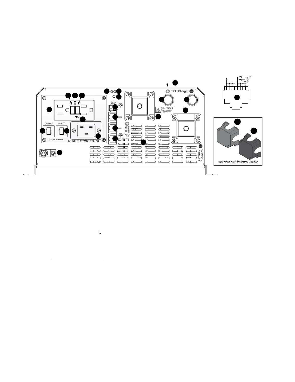
2.1 LAYOUT OF EVO-1212F AND EVO1224F – FRONT VIEW
Legend for Fig 2.1
1. Battery Positive (+) Input Connector (marked "BATTERY POSITIVE"): Stud and Nut, M8 (Pitch 1.25 mm)
• 1a Red Protective Cover for Battery Positive (+) Input Connector – mounted using 2 pcs of M3 (Pitch 0.5 mm) x 10 mm long screws
2. Battery Negative (-) Input Connector (marked "BATTERY NEGATIVE"): Stud and Nut, M8 (Pitch 1.25)
• 2a Black Protective Cover for Battery Negative (-) Input Connector - mounted using 2 pcs of M3 (Pitch 0.5 mm) x 10 mm long screws
3. External Charge Controller Positive (+) Input Connector (marked "+ EXT. charger"): Stud and Thumb Nut, M6 (Pitch 1 mm)
4. External Charge Controller Negative (-) Input Connector (marked "– EXT. charger"): Stud and Thumb Nut, M6 (Pitch 1 mm)
5. DC Side Ground Connector (marked "
") – Hole Diameter 6.5 mm for AWG #4 to #6; Set screw M6 (Pitch 0.75 mm)
6. RJ-45 Jack marked "Battery Temp. Sensor"(Pinout at 19) is used for 2 functions as follows:
a) Connecting Battery Temperature Sensor “EVO-BCTS”[Fig 2.5(a)] for temperature compensation when Parameter "BATTERY TYPE"is
set for option "0=Lead Acid", or
b) Connecting potential free contact switching signal from Lithium Ion Battery Management System (BMS) to stop charging/ stop
inverting [See Sections 3.16 & 5.11.2]
7. RJ-45 Jack (marked "Remote Control") for “EVO-RC Plus” Remote Control
8. RJ-45 Jack (marked "COMM") - for future use.
9. Male AC Power Inlet Plug – Rating 20A (IEC60320 C-20). Will require 20A rated Female Socket
Connector (IEC 60320 C-19). For convenience, the connector has been supplied with the unit
(See Section 2.6 – “Contents of Package”)
10. NEMA5-15R Duplex GFCI Outlets for 120 VAC output [See Section 3.6.1.2 for details].
• 10a. Test Button • 10c. Red LED: GFCI Life End Alarm
• 10b. GFCI Reset Button • 10d. Green LED: GFCI ON
11. ON/Off Push Button
12. Blue LED “ON”
13. Red LED “Fault”
14. AC output Breaker, 15A
15. AC Input Breaker, 20A
16. Connector (marked "Remote On/Off") for On/Off Control through external +12V signal (9 – 15V, < 10mA):
Screw M2.5; Wire size AWG#30 to AWG#12. Refer to Section 6.2 for details.
• CAUTION! Observe correct polarity - Upper terminal is Negative and Lower terminal is Positive
17. Air inlet vents for 2 variable speed, temperature controlled cooling fans.
18. Removable top cover: Fixed with 8 screws – M4 (Pitch 0.7mm) x 4 mm
19. Pinout for RJ-45 Jack marked "Battery Temp. Sensor"(6, Fig 2.1)
SECTION 2 | Components & Layout
Fig 2.1 Layout of Front side EVO-1212F / EVO-1224F
5
6
9
17
14 15
18
1
2
3 4
8
7
10
11
16
1213
10a 10b10c
10d
1 2 3 4 5 6 7 8
+5V
Batt Temp
to DSP
1K
5.1K
RJ-45 Jack (for Battery Temp. Sensor - Pinout)
N L
G
19
1a
Red
2a
Black