72 | SAMLEX AMERICA INC.
SECTION 3 | Installation
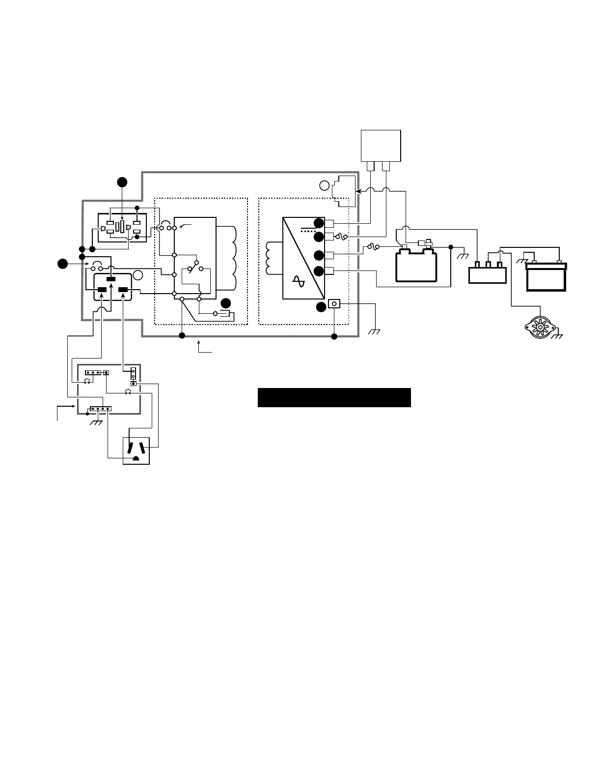
Fig 3.14 Installation Diagram for Typical RV / Mobile Installation for
EVO-1212F and EVO-1224F
+
-
+
-
+
-
A.C. Section
D.C. Section
+
-
Battery
Bank
EVO INVERTER CHARGER: EVO-1212F AND EVO-1224F
External
Charge
Controller
RJ-45
6
J6
RY2
J7
J1
J2
J9
J4
9
Metal Chassis
G
G
G
NL
+ + +
- +
Battery Isolator
Engine Starter
Battery
Alternator
G-B
L-B L
120V, SINGLE
PHASE ELECTRICAL
PANEL OF RV
30A Service Inlet for 30A
RV Power Supply Cord
NEMA TT-30P
G
NL
N-B
N
See LEGEND on the next page
4
3
2
1
5
10
15
BCTS
27
LEGEND FOR FIG 3.14
NOTE:
For sizing of wiring and fuses, refer to the following:
a) DC side wiring: Table 3.1
b) AC side wiring: Table 3.2
L. Line Terminal
L-B. Line Bus Bar
N. Neutral Terminal
N-G. Neutral to Ground Bond
N-B. Neutral Bus Bar
G-B. Grounding Bus Bar
SBJ. System Bounding Jumper
J1, 2, 4, 7, 9 Male Tab Terminals on internal Circuit Board
RY2. Relay for Neutral to Ground Bond Switching (Section 4.4.2)
BCTS. Battery Charger Temperature Sensor EVO-BCTS [Fig 2.5(a)]
1. Battery Positive Input Connector (1, Figs 2.1 / 3.8)
2. Battery Negative Input Connector (2, Figs 2.1 / 3.8)
3. Positive Input Connector for External Charge Controller (3, Figs 2.1 / 3.8)
4. Negative Input Connector for External Charge Controller (4, Figs 2.1 / 3.8)
5. DC Side Grounding Terminal on EVO™ (5, Figs 2.1/ 3.8)
6. RJ-45 Jack for Temperature Sensor (6, Fig 2.1)
GE. Grounding Electrode. Also called "Ground Rod"
9. 20A Inlet Plug Connector IEC 60320 C20 (9, Fig 2.1)
10. NEMA5-15 Duplex GFCI Outlets (10, Fig 2.1)
14. 15A Built-in Breaker for AC output (14, Fig 2.1)
15. 20A Built-in Breaker for AC input (15, Fig 2.1)
27. "Quick Disconnect" to disconnect Neutral to Ground bond (27, Fig 3.9.2)
Circuit breaker
Fuse
120 VAC Leg, Phase A
120 VAC Leg, Phase B (180° out of phase with Phase A Leg)
WARNING!
In case a Generator is used to feed AC input, please ensure that the Neutral conductor of the Generator is
bonded to the chassis / frame of the Generator. Please refer to Section 3.14.1 for details.
MISE EN GARDE!
En cas d'un générateur est utilisé pour envoyer de l'entrée CA, veuillez vous assurer que le conducteur
neutre de la génératrice est collé sur le châssis / cadre de la génératrice. Veuillez vous reporter à la
section 3.14.1 pour plus de détails.