SAMLEX AMERICA INC. | 39
3.4.3 Series – Parallel Connection
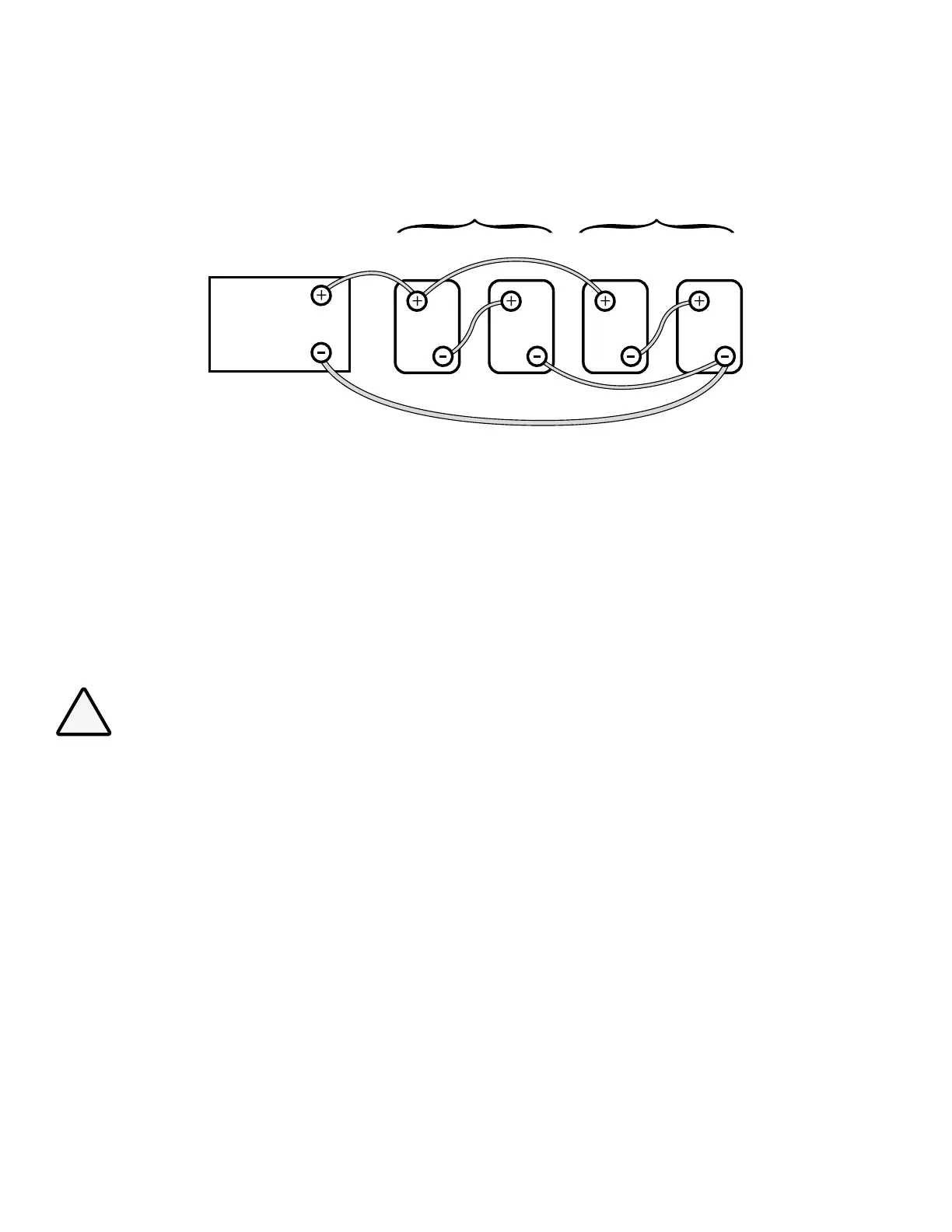
6V 6V 6V 6V
12V String 1 12V String 2
Battery 1 Battery 3Battery 2 Battery 4
12V Inverter
or 12V Charger
Cable “A”
Cable “B”
Fig. 3.7 Series-Parallel Connection
Figure 3.7 shows a series – parallel connection consisting of four 6V, 200 Ah batteries to form a 12V, 400 Ah battery
bank. Two 6V, 200 Ah batteries, Batteries 1 and 2 are connected in series to form a 12V, 200 Ah battery (String 1).
Similarly, two 6V, 200 Ah batteries, Batteries 3 and 4 are connected in series to form a 12V, 200 Ah battery (String 2).
These two 12V, 200 Ah Strings 1 and 2 are connected in parallel to form a 12V, 400 Ah bank.
3.4.4 Wiring Order in Parallel Connection of Batteries
CAUTION!
When 2 or more batteries / battery strings are connected in parallel and are then connected to inverter/
charger (See Figs 3.6 and 3.7), attention should be paid to the manner in which the inverter/charger is
connected to the battery bank. Please ensure that if the Positive output cable of the inverter/charger
(Cable “A”) is connected to the Positive battery post of the rst battery (Battery 1 in Fig 3.6) or to the
Positive battery post of the rst battery string (Battery 1 of String 1 in Fig. 3.7), then the Negative output
cable of the inverter/charger (Cable “B”) should be connected to the Negative battery post of the last
battery (Battery 4 as in Fig. 3.6) or to the Negative Post of the last battery string (Battery 4 of Battery String
2 as in Fig. 3.7). This connection ensures the following:
- The resistances of the interconnecting cables will be balanced.
- All the individual batteries / battery strings will see the same series resistance.
- All the individual batteries will charge/discharge at the same charging/discharging current and thus,
will be charged/discharged to the same state at the same time.
- None of the batteries will see an overcharge/overdischarge condition.
If the Positive output cable of the inverter/charger (Cable “A”) is connected to the Positive battery post of
the rst battery (Battery 1 in Fig. 3.6) or to the Positive battery post of the rst battery string (Battery 1 of
String 1 in Fig. 3.7), and the Negative output cable of the inverter/charger (Cable “B”) is connected to the
Negative battery post of the rst battery (Battery 1 as in Fig. 3.6) or to the Negative Post of the rst battery
SECTION 3 | Installation