SAMLEX AMERICA INC. | 41
SECTION 3 | Installation
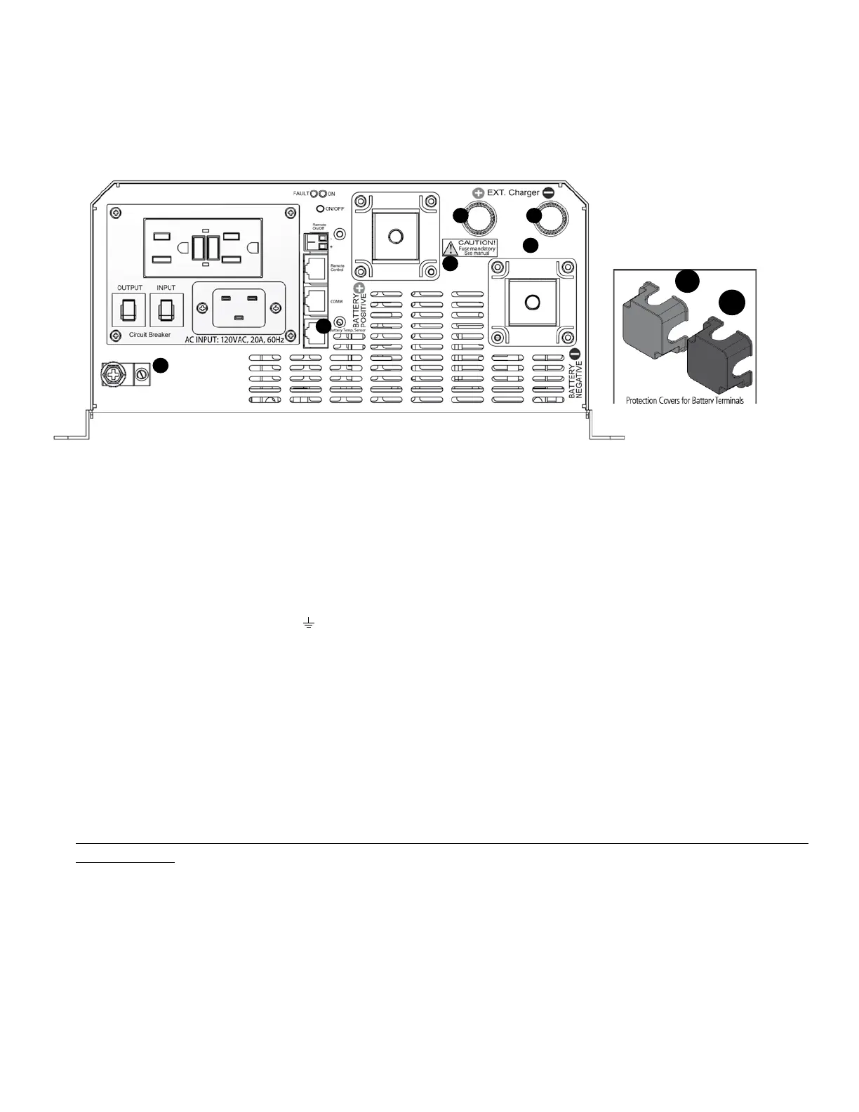
3.5 DC SIDE CONNECTIONS
1
2
3 4
5
6
1a
Red
2a
Black
Fig 3.8 D.C Side Connections
LEGEND for Fig 3.8
1. Battery Positive (+) Input Connector (marked "BATTERY POSITIVE"): Stud and Nut, M8 (Pitch 1.25 mm) (RED Protection Cover 1(a) is
removed)
1a. RED Protection Cover For Battery Positive (+) Input Connector
2. Battery Negative (-) Input Connector (marked "BATTERY NEGATIVE"): Stud and Nut, M8 (Pitch 1.25 mm) (Black Protection Cover 2(a)
is removed)
2a. Black Protection Cover for Battery Negative (-) Input Connector
3. External Charger (+) Input Connector (marked "+ EXT. charger"): Stud and Nut, M6 (Pitch 1 mm)
4. External Charger (-) Input Connector (marked "– EXT. charger"): Stud and Nut, M6 (Pitch 1 mm)
5. DC Side Grounding Connector (marked "
") Hole Dia 6.5 mm for up to 25 mm2 (AWG #4). Set Screw M-8. This is internally
connected to the metal chassis of the unit
6. RJ-45 Jack (marked "Battery Temp. Sensor") is used for 2 functions as follows:
a. For input from Temperature Sensor "EVO-BCTS" for temperature compensation when Battery Type 0 = Lead Acid is selected or,
b. For input for contact closure / opening signal from the Battery Management System (BMS) to Pins 4 and 5 of the Jack when Battery
Type 1 = Lithium is selected. When pins 4 and 5 are shorted due to contact closure, charging will stop in "Charging" Mode and
inverting will stop in "Inverting" Mode
3.5.0 Making DC Side Connections
The following DC side connections are required to be made (see Fig 3.8):
Deep cycle batteries are connected to the battery input terminals (1) and (2). The terminals are provided with
protective covers – RED for Positive and BLACK for Negative. Fit these covers once connections have been made.
For general details on sizing and charging of batteries, please refer to Section 1.4 under "General Information-Lead
Acid Batteries".
Use appropriate external fuse (Refer to Table 3.1) within 7” of battery Positive terminal.
External charging source, if any, is connected to the connectors (3) and (4) as shown above. The maximum
capacity of the external charging source is 50A.
Battery Temperature Sensor EVO-BCTS is connected to the RJ-45 Jack (6). See Fig 2.5 (a) and 2.5 (b) for details.
DC Side Grounding Connector (5) is connected to the Earth ground / vehicle chassis ground as follows using
minimum AWG #6 wire size:
(i) to the Bus Bar "G-B" of the DC Electrical Panel (Fig 3.12)
(ii) to the Bus Bar "G-B" of the Grid Electrical Panel (Fig 3.13)
(iii) to the RV chassis ground in RV (Figs 3.14A and 3.14B)