SAMLEX AMERICA INC. | 45
SECTION 3 | Installation
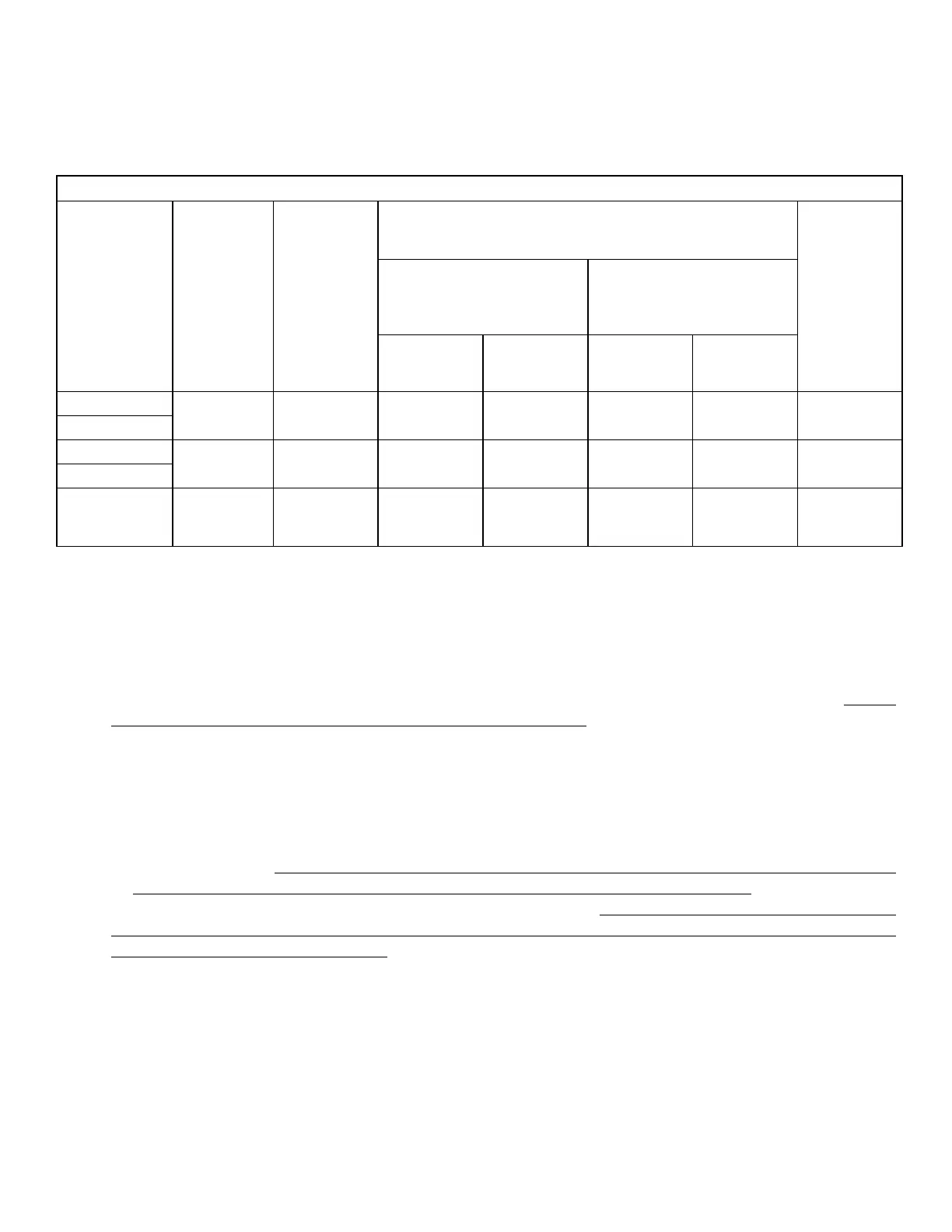
TABLE 3.1 SIZING OF BATTERY SIDE CABLES AND EXTERNAL BATTERY SIDE FUSES
Model No.
(Column 1)
Rated
Continuous
DC Input
Current
(See Note 1)
(Column 2)
NEC Ampac-
ity = 125%
of Rated DC
Input Current
at Column 2
(See Note 2)
(Column 3)
90°C Copper Conductor. Size Based on NEC Ampacity
at Column (3) or 2%Voltage Drop, whichever is Thicker
(See Note 3)
External Fuse
Based on NEC
Ampacity at
Column (3)
(See Note 4)
(Column 8)
Cable Running Distance
between the Unit and
the Battery
(Cable Routing In Free Air)
Cable Running Distance
between the Unit
and the Battery
(Cable Routing In Raceway)
Up to 5 ft.
(Column 4)
Up to 10 ft.
(Column 5)
Up to 5 ft.
(Column 6)
Up to 10 ft.
(Column 7)
EVO-1212F
152 190 AWG #2 AWG #2/0 AWG #2/0 AWG #2/0 200A
EVO-1212F-HW
EVO-1224F
76 95 AWG#6 AWG#4 AWG#3 AWG#3 100A
EVO-1224F-HW
External Charger 50A 63A
AWG #6
(2% voltage
drop is thicker)
AWG #2
(2% voltage
drop is thicker)
AWG #6
AWG #2
(2% voltage
drop is thicker)
70A
NOTES FOR TABLE 3.1 - SIZING OF BATTERY SIDE CABLES AND EXTERNAL BATTERY SIDE FUSES
1) Column 2 indicates the Rated Continuous DC Input Current drawn from the battery in Inverter Mode
2) Column 3 indicates NEC Ampacity based on which cable conductor sizes (Columns 4 to 7) are determined.
NEC Ampacity is not less than 125% of the Rated Continuous DC Input Current (Column 2) - Refer to NEC-
2014 (National Electrical Code) - Section 215.2(A)(1)(a) for Feeder Circuits.
3) Columns 4 to 7 indicate cable conductor size that is based on the following 2 considerations. Thicker
conductor out of the following 2 considerations has been chosen:
a) As per guidelines in NEC-2014 (National Electrical Code) - Ampacity Table 310.15(B)(16) for Raceway
and Ampacity Table 310.15(B)(17) for Free Air. Conductor size is based on (i) NEC Ampacity specied at
Column 3, (ii) Copper conductor with temperature rating of 90°C and (iii) Ambient temperature of 30°C
/ 86°F
b) Voltage drop across the length of cables has been limited to 2% of 12V / 24V. Voltage drop has been
calculated by multiplying the Rated DC Input Current (Column 2) and the resistance of the total length of
Copper conductor (the total length of conductor has been taken as 2 times the running distance between
the unit and the battery to cover 2 lengths of Positive and Negative cable conductors).
4) Column 8 indicates the size of external fuse in the battery circuit. It is mandatory to install this fuse within
7” of the battery Positive terminal to protect the internal DC Input Section of the unit and also to protect
the battery cables against short circuit. Ampere rating of the fuse is based on the following considerations:
a) The Ampere rating of the fuse is not less than NEC Ampacity of 125% of the Rated Continuous DC Input
Current (Column 3) - Refer to NEC-2014 (National Electrical Code) - Section 215.3
b) Standard Ampere Rating of Fuse equal to the above NEC Ampacity of 125% of the Rated DC Input
Current has been used - Refer to NEC-2014 (National Electrical Code) - Section 240.6(A)
c) Where Standard Fuse Rating does not match the required Ampacity of 125% of the Rated Continuous DC
Input Current (Column 3), the next higher Standard Rating of the fuse has been used - Refer to NEC-2014
(National Electrical Code) - Section 240.4(B)
d) Type of fuse: Fast-acting, Current Limiting, UL Class T (UL Standard 248-15) or equivalent