80 | SAMLEX AMERICA INC.
SECTION 4 | General Description & Principles of Operation
NEUTRAL
BI-DIRECTIONAL
TRANSFORMER
LINE
RY2
RY1
METAL CHASSIS
GROUND OF THE EVO
TM
3
4
5
3
4
5
INVERTING
CHARGING
OUTPUT N
INPUT L
INPUT
INPUT N
OUTPUT L
OUTPUT
27
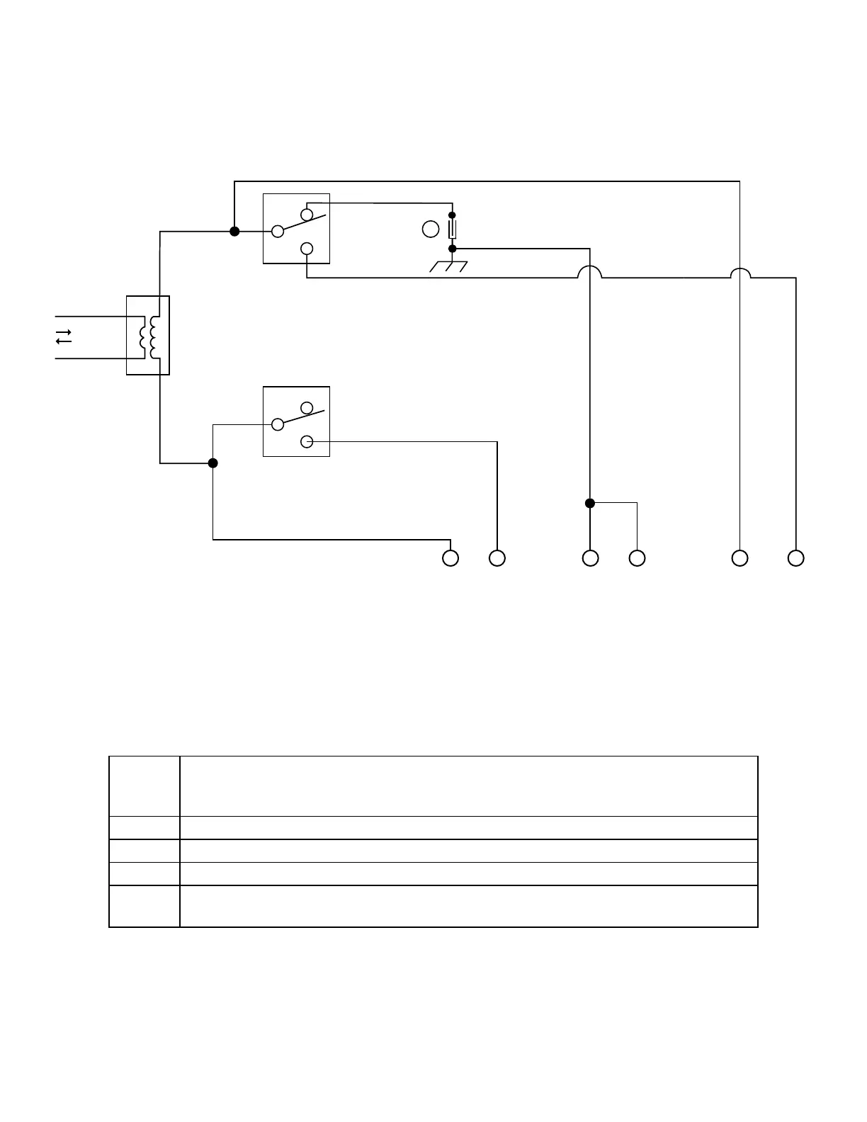
Fig 4.1 Operation of Transfer Relay and Switching of Bond Between
Output Neutral and Metal Chassis Ground
LEGEND for Fig 4.1
RY1 Transfer Relay (40A - See Note 2 below) (Shown in de-energized state). Transfers the
Line Conductor of the AC load to either the Line Conductor of the input from Grid /
Generator or to the Line Conductor of the Inverter Section.
RY2 Relay (40A - See Note 2 below) for Neutral to Ground bond Switching
4, 3 Normally Closed Contacts (Shown in de-energized state)
4, 5 Normally Open Contacts (Shown in de-energized state)
27
Insulated Male / Female Quick Disconnect [27, Fig 3.9.2(a)] for disconnecting
Output Neutral to Chassis Ground bond in Inverting Mode (Default - connected)
NOTES: 1. Relays are de-energized in Inverting Mode and are energized in Charging Mode.
2. Although relays RY1, RY2 are rated for 40A, AC input current and output pass
through current in charging mode are limited to 20A & 15A respectively by the
20A input breaker and 15A output breaker.