3-4 EB 8340 EN
Design and principle of operation
Inductive limit contacts
Optionally, the actuator can be equipped
with a maximum of two inductive contacts.
They are no-wear NC contacts, which are
usedtoinuencethetasksofcontrolequip-
ment.Isolatingswitchampliersaccordingto
EN50227mustbeinstalledintheoutputcir-
cuit for the operation of inductive limit con-
tacts.
The inductive limit contacts are not suitable
forretrotting.
Resistance transmitters
The actuator version three-step control can
optionally be equipped with one or two po-
tentiometers. They are linked to the gear of
the actuator. They consist of one potentiome-
ter, which produces a resistance signal be-
tweenapprox.0and1000Ω(usablerange
0to900Ω)proportionaltothetravel.Itcan
be used to assess the position of the actuator
stem. The resistance transmitters are suitable
forretrotting.Theinstallationandadjust-
ment of the mechanical limit contacts is de-
scribed in the 'Installation' section.
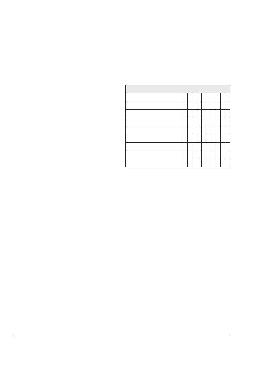
3.3.1 Combination of options
Theactuatorcanbettedwiththefollowing
options:
Table3-1: Combination of options
Accessories
Positioner
• •
Position transmitter
• •
Resistance transmitter 1
1)
• • • • • • • •
Resistance transmitter 2
• • • • • •
Mechanical limit contact 1
• •
Mechanical limit contact 2
• • • • •
Mechanical limit contact 3
• • • • •
Inductive limit contact 1
• • • • •
Inductive limit contact 2
• • • • •
1)
Internal use (with positioner and position transmitter)