7-6 EB 8340 EN
Start-up
7.3 Calibrating the position transmitter
1. Set the slider switches SW3 and SW4 depending on the required position feedback sig-
nal (see Table 7-1):
SW3andSW4toON:4to20mA/2to10V
SW3andSW4toOFF:0to20mA/0to10V
2. Connect an ammeter to terminals 31 (+) and 32 (–) or a voltmeter to terminals 32 (–) and
33 (+) (in this case, after jumpering the terminals 31 and 32).
3. Move the actuator stem to the lower end position (manually or by entering an input sig-
nal).
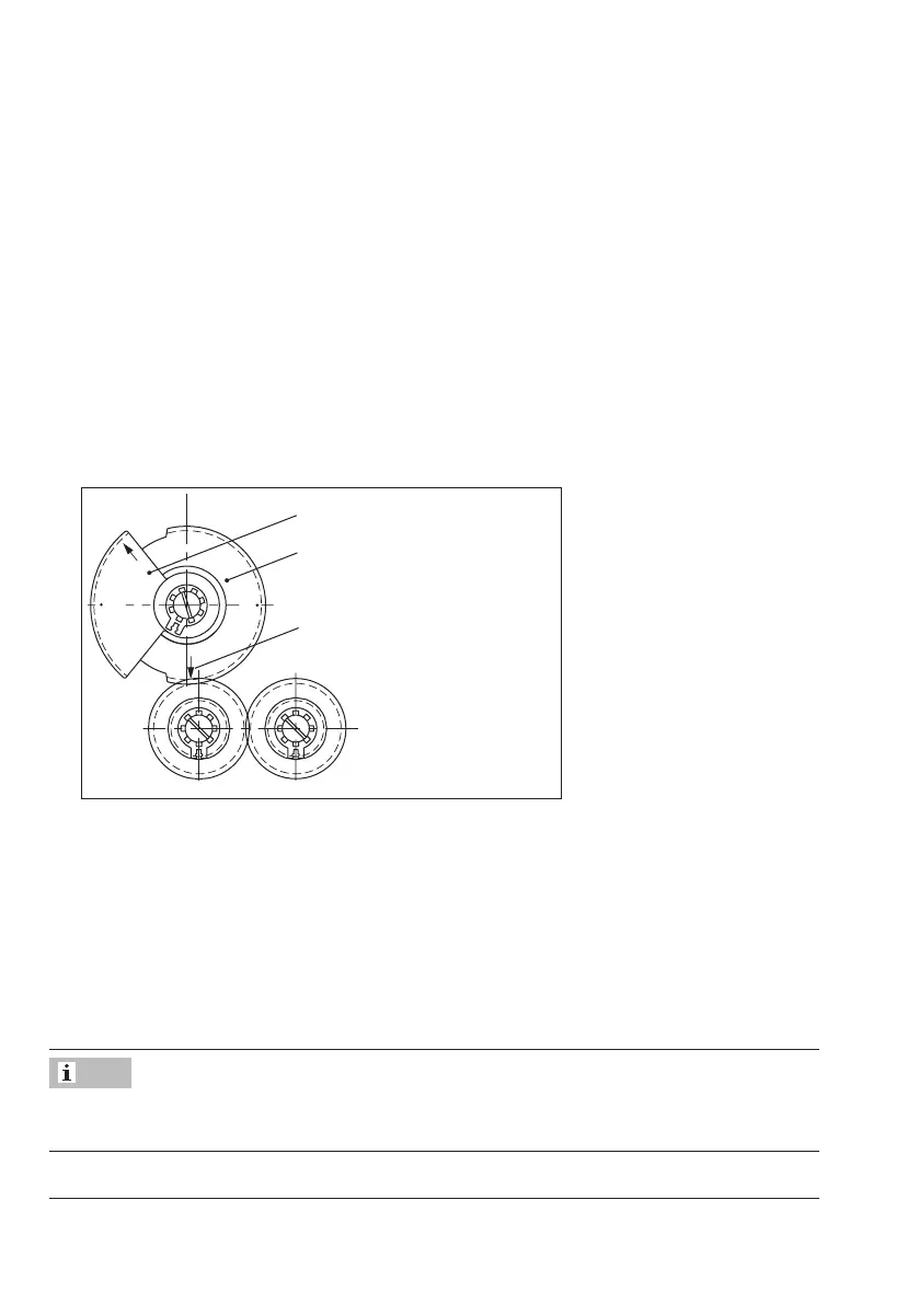
4. Position the segment gear S1 with the corresponding arrow tip depending on the valve
ratedtravel(15or30mm)pointingtowardstheaxisofthepotentiometerP1.
15
30
S1
Segmentfor15mmtravel
Segmentfor30mmtravel
Position of the arrow when the
actuator stem is fully extended
5. Hold the segment gear S1 and turn the axis of potentiometer P1 clockwise using a suit-
able screwdriver as far as it will go.
6. Turn axis of potentiometer P1 counterclockwise until the required value for the lower end
position is measured.
7. Move the actuator stem to the top end position (manually or by entering an input signal).
8. The value for the top end position should be indicated on the measuring instrument. It
can be adjusted with the 'Span out' adjuster.
To reverse the characteristic, swap over the connecting wires (green and white) at the termi-
nals eL and aL.
Note