7-8 EB 8340 EN
Start-up
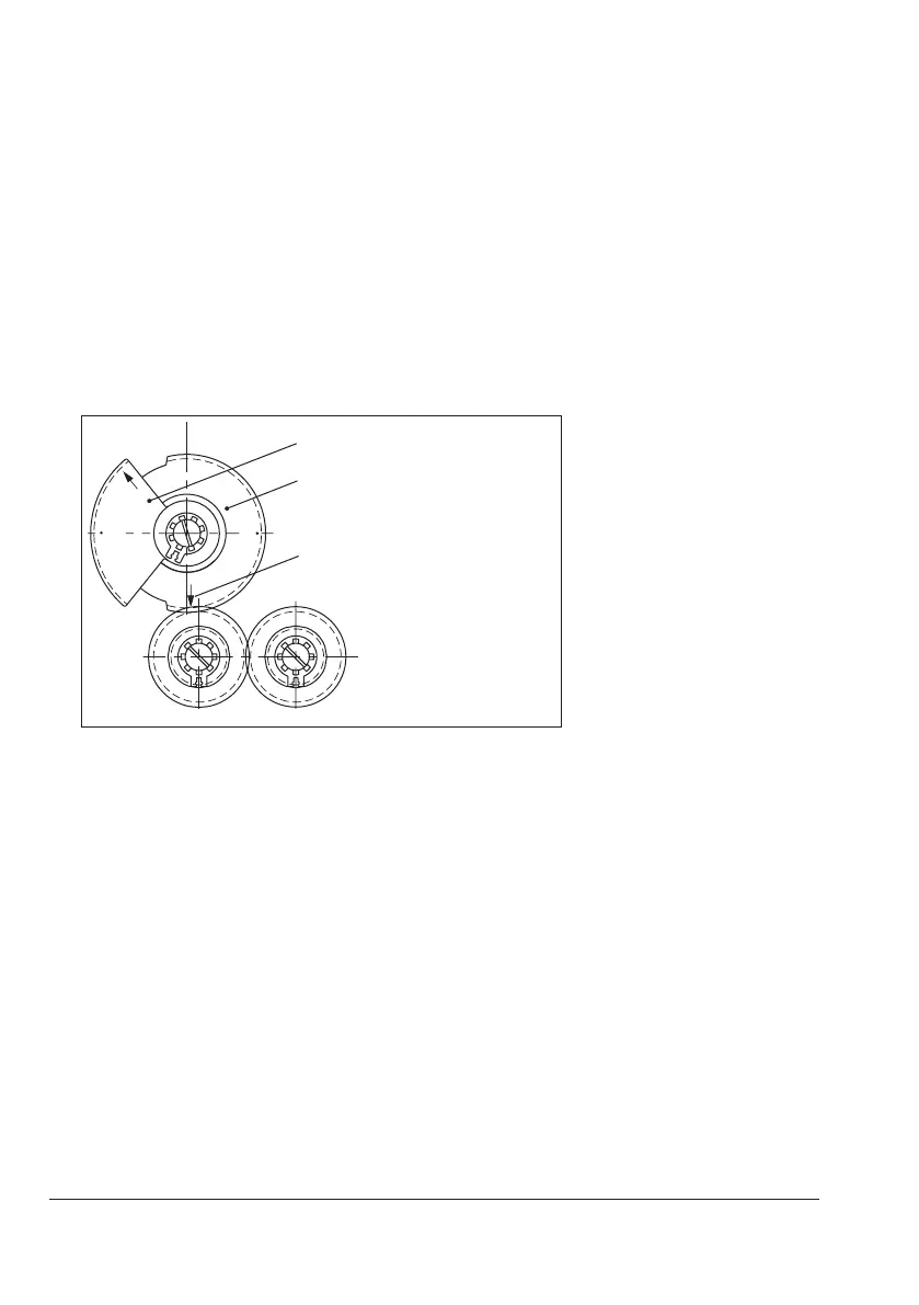
7.5 Adjusting the resistance transmitter
The actuator can be equipped with two resistance transmitters at the maximum. Potentiometer
P1 is required for internal position feedback in actuators with positioner or position transmit-
ter. Therefore, external position feedback cannot be used in this case.
PotentiometerP1:
1. Move the actuator stem to the lower end position.
2. Position the segment gear S1 with the corresponding arrow tip depending on the valve
ratedtravel(15mmor30mm)pointingtowardstheaxisofthepotentiometerP1.
15
30
S1
Segmentfor15mmtravel
Segmentfor30mmtravel
Position of the arrow when the
actuator stem is fully extended
3. Hold the segment gear S1 and turn the axis of potentiometer P1 clockwise using a suit-
able screwdriver as far as it will go.
PotentiometerP2:
Potentiometer P2 is driven by the pinion of potentiometer P1. Opposed resistance values
arise as a result.
Î Set as described for P1.
Î Turn potentiometer P2 counterclockwise as far as it will go.