7
Start-up – Settings
WARNING!
Attach the positioner, keeping the following
sequence:
1. Mount the positioner on the control valve
2. Connect the supply air
3. Connect the electrical power
4. Perform the start-up settings
Reading on display after connecting the
electrical auxiliary power:
4
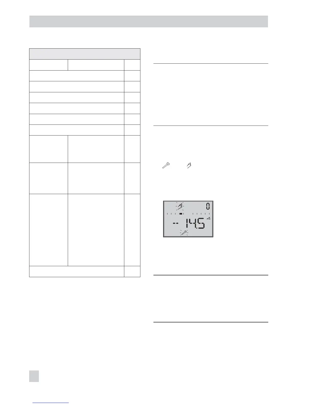
tEStinG runs across the display and then
and blink on the display when
the positioner has not yet been initial-
ized. The reading indicates the lever po-
sition in degrees in relation to the longi-
tudinal axis.
Reading when the
positioner has not yet
been initialized
4
Code 0 appears on the display when a
positioner has been initialized. The
positioner is in the last active operating
mode.
WARNING!
The actuator stem moves while the start-up
settings are being performed.
Do not touch the actuator stem or obstruct it
to avoid risk of injury to hands or fingers.
46 EB 8387-3 EN
Start-up – Settings
Assignment of dynamic HART
®
variables
Variable Meaning Unit
Set point %
Direction of action set point %
Set point after transit time specification %
Valve position %
Set point deviation e %
Absolute total valve travel –
Binary input
status
0 = Not active
1 = Active
255 = –/–
–
Internal
solenoid
valve/forced
venting status
0 = De-energized
1 = Energized
2 = Not installed
–
Condensed
state
0 = No message
1 = Maintenance
required
2 = Maintenance
demanded
3 = Failure
4 = Out of
specification
7 = Function check
–
Temperature °C