9-2 EB 8359-2 EN
Servicing
9.1 Changing the operating di-
rection of the positioner
control loop
To change the operating direction of the po-
sitioner control loop (increasing/increasing,
increasing/decreasing):
Î Change the operating direction of the
positioner control loop (see the 'Installa-
tion' section).
Î Determine on which side of the valve the
positioner is to be mounted (see the 'In-
stallation' section).
9.2 Converting the electro-
pneumatic into a pneu-
matic positioner
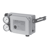
Fig.9-1
The electropneumatic positioner can be con-
verted into a Type4765 Pneumatic Position-
er with a conversion kit.
Î Required conversion kits: see Table 9-1
1. Unscrew fastening screws and lift the i/p
converter together with the printed circuit
board out of the positioner housing.
2. Unthread cable gland (1). Plug on hose
(5) and screw the connecting nipple (4)
of the conversion kit tightly on the hous-
ing.
3. Insert sealing element (7) into connecting
plate (6) and fasten it tight into the hous-
ing.
4. Push the free end of the hose onto the
connecting plate (6).
For details on the converted Type4765 Posi-
tioner refer to Mounting and Operating In-
structions u EB8359-1.
Table 9-1: Conversion kits
Device index Threaded
connection
Order no.
0.2 G 1400-6724
NPT 1400-6725
0.3 G 1400-6795
NPT 1400-6796
9.3 Periodic inspection and
testing of the positioner
We recommend inspection and testing ac-
cording to Table 9-2 at the minimum.
Note