57
AA
ENGLISH
1. Before supplying the power, use DC 500 V insulation resistance tester to measure the power (3 phase: R, S, T/ 1 phase: L, N)
terminal and the outdoor unit grounding.
- Measurement should be over 30MΩ.
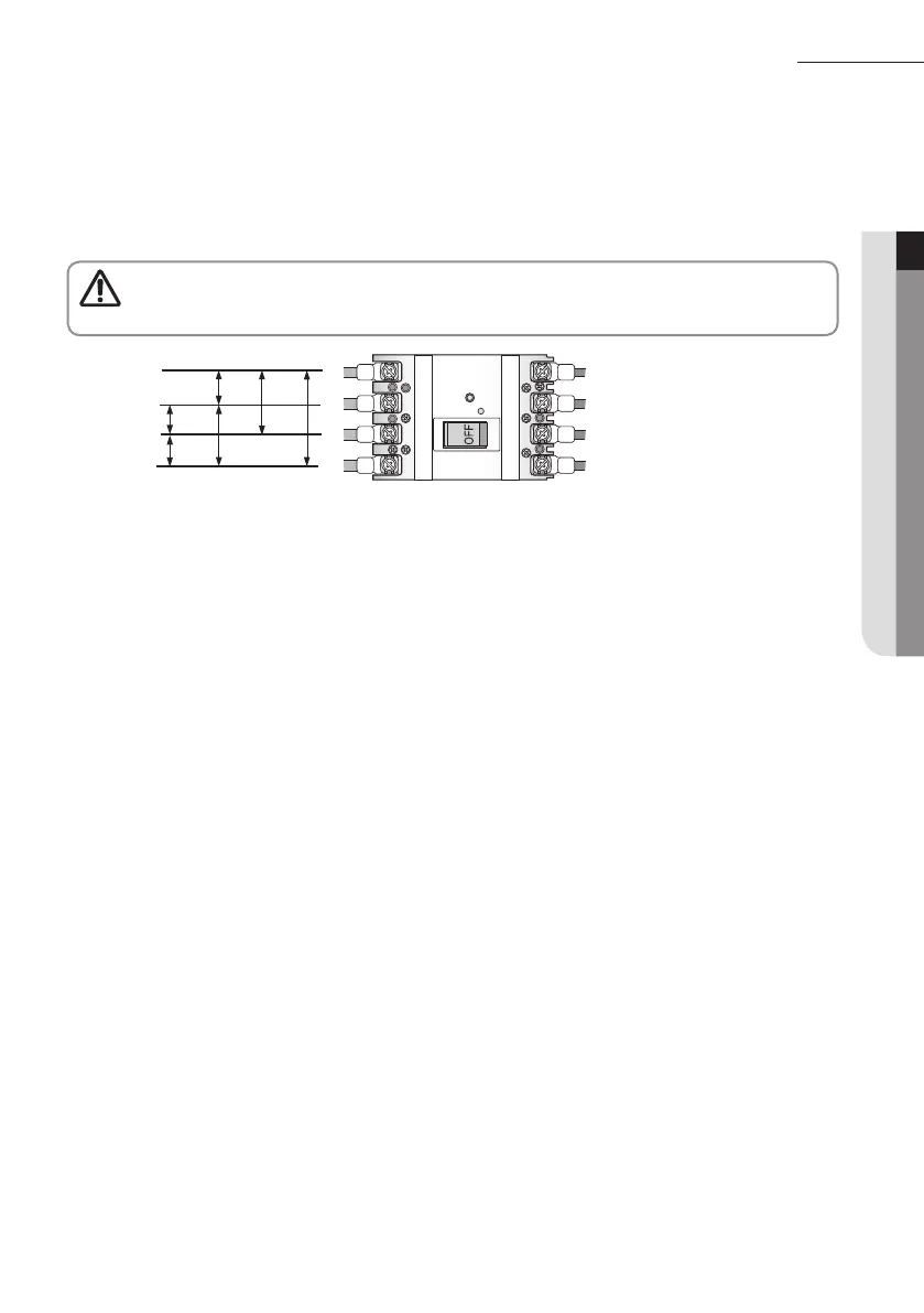
2. Before supplying the power, use a voltmeter and phase tester to check the voltage and the phase.
- R, S, T, N terminal: check if the voltage is within 380-415V between wires (R-S, S-T, T-R) and 200-240V between phases
(R-N, S-N, T-N) before turning on the switch.
Caution
• Never measure the communication terminal since communication circuit may get damaged.
• Check for short-circuit of the communication terminal with a general circuit tester.
N
T
S
R
< ELB >
230V
400V400V
400V
230V 230V
3. Check if the R-410A indoor units are connected.
4. When N phase is not correctly connected to R, S and T phase, over-voltage protection control will be in effect and it will
cut-off the power of the PCB. Check the power cable connection of the N phase if the PCB is not turned on.
5. Check the following after the installation is completed.
Things to check after completing the installation
 Loading...