LED R&D Lab(VD)
33
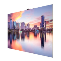
Fig.7 (check the gap)
Fig.8 (adjust the gap)
• Install the Frame Center after a Frame Side and two Frame Middles are installed based on the VG-LFR53FWL.
• Before installing Frame Middle next to the Frame Center, be sure to hang the IER Cabinet on the bottom line.
• Push the modules to the center and check the Frame Center so that there is no gap between cabinets and
between modules.
• When the module’s end is protruded more than 0.5 mm to the right based on the Frame Center, adjust the right
side of Frame Center outward.
• When the module’s end is protruded within 0.0 mm to the right based on the Frame Center, adjust the right side
of Frame Center inward.
• When installed long left to right, repeat the above procedure whenever a Frame Center is installed.
※ Otherwise, it may cause maintenance issues due to difficulty in attachment and detachment of a module.
Excessive attachment may cause the module’s dislocation. (see page 27)
◆Bracket Center’s usable section,
VG-LFR53FWL: Every 3 rows
VG-LFR52SWL: Every 3 rows
VG-LFR84FWL: Every 4 rows
LED Module
Gap is within 0.0 mm
Gap is over 0.5 mm
Cabinet
Gap
Gap
4. Frame Installation– Adjusting the Frame Center (Important)
 Loading...