Contents
4. Troubleshooting ....................................................................................50
4-1) Function for failure diagnosis ....................................................................................................................... 51
4-1-1. Test mode (manual operation / manual defrost function) ............................................................ 51
4-1-2. Display function of Communication error ...................................................................................... 52
4-1-3. Self-diagnostic function ................................................................................................................. 53
4-1-4. Display function of Load condition ................................................................................................ 56
4-1-5. Exhibition mode setting function .....................................................................................................57
4-1-6. Option setting function .................................................................................................................... 58
4-1-7. Option TABLE .................................................................................................................................. 60
4-2) Diagnostic method according to the trouble symptom(Flow Chart) ....................................................... 62
4-2-1. If the trouble is detected by self-diagnosis ................................................................................. 64
4-2-2. If FAN does not operate .................................................................................................................75
4-2-3. If ICE Room Fan does not operate ................................................................................................76
4-2-4. When ICE MAKER(FF) does not operate ......................................................................................77
4-2-5. When ICE MAKER(FZ) does not operate ......................................................................................78
4-2-6. If defrost does not operate (F,R DEF Heater) ...............................................................................79
4-2-7. When Power is not applied ........................................................................................................... 80
4-2-8. When Compressor does not run (Inverter COMP.) .....................................................................81
4-2-9. When alarm sounds continuously without stop(related with buzzer sound) ............................ 82
4-2-10. When the Panel PCB does not operate normally ..................................................................... 84
4-2-11.
If Pantry Panel PCB is not working normally ............................................................................................... 85
4-2-12. When refrigerator ROOM Lamp does not light up ..................................................................... 86
4-2-13. If ICE Water is not supplied ...........................................................................................................87
4-2-14. If Cubed or Crushed Ice is not supplied .................................................................................... 89
4-2-15. If Cover Ice Route Motor(Geared Motor) is not working normally ........................................... 90
4-2-16. IR Sensor Trouble-Shooting .........................................................................................................91
4-2-17. LED blinking frequency depending on protecting functions .................................................... 92
SPM FREEWHEELING DIODE VOLTAGE VALUE ...................................................................................... 93
5. Pcb Diagram .........................................................................................94
5-1) PCB Layout with part position ................................................................................................................... 95
5-2) PCB Layout with part position (Inverter Board) ....................................................................................... 96
5-3) Connector Layout with part position (Main Board) ..................................................................................97
5-4) Connector Layout with part position (Inverter Board) .............................................................................. 98
6. Wiring Diagram .....................................................................................99
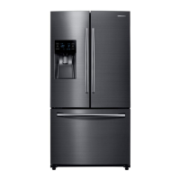
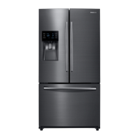
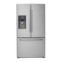
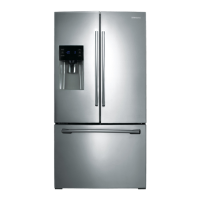
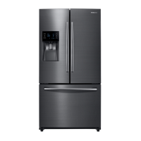
6-1) Model : RF263TEAE**, RF263BEAE** ....................................................................................................... 99
7. Schematic Diagram .............................................................................. 100
7-1) Whole block diagram ..................................................................................................................................100
7-2) Whole block diagram.................................................................................................................................. 101
7-3) CIRCUIT DIAGRAM ......................................................................................................................................102
7-3-1. Main .................................................................................................................................................102
7-3-2. INVERTER .......................................................................................................................................103