71
8) If Ice Room Sensor has trouble
Bad contact of connector/ insert correctly
Is MAIN PCB
Connector CN78 and CN76 inserted
correctly?
Is
Ice room sensor unit
normal?
Is the voltage between
MAIN PCB Connector CN78-"10"(Orange) and
J23 JUMMPER normal?
Is the input voltage of
IC01 MICOM #92 normal?
Start
NO
YES
YES
YES
YES
Replace temperature sensor
NO
Check the wiring connection
NO(0.6V > Measurement < 4.6V)
Check the iced-solder, solder
bridging, disturbed solder
NO
No trouble with PCB and temperature sensor.
Check the bad connections.
** Measuring point of resistance value according to
Sensor **
Ambient : CN78 ”10”↔ CN76-”1” Measure the voltage
of Resistance value
** 0Ω: Short trouble /Ω∞: Open trouble
Sensor MICOM/Connector number
Voltage measured between 4.6V ~ 0.6V.
Measuring voltage of IC01 MICOM #92,
CN78-"10"(Orange) and J23 JUMMPER from
PCB Typical Ground are similar.
→ Check the measure on the voltage of Resistance,
R316 due to the SMD MICOM
☞
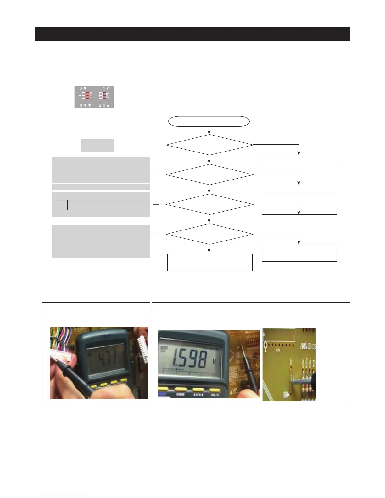
Checking Mehod of Ice Room Sensor voltage
CN78-"10"(Orange)↔ CN76-”1” (Gray)
- Compare with the temperature table after
measurement.
DATA1.
Temperature table
ERROR Code
Refer to the circuit diagram in this manual
Ice Room
Connector CN78-"10"(Orange) and
J23 JUMMPER from PCB Typical Ground
☞
Checking Method of Ice Room Sensor Voltage
- Measure the voltage of Resistance, R316(IC01 MICOM #92) on PCB or
CN78-"10"(Orange)
↔J23 JUMMPER
- Compare with the temperature table after measurement.
Measured voltage of CN78-"10"(Orange)
↔ J23 JUMMPER are as below
PCB Typical Ground
J23 JUMMPER
Start
YES
YES
YES