12 S&C Instruction Sheet 461-502
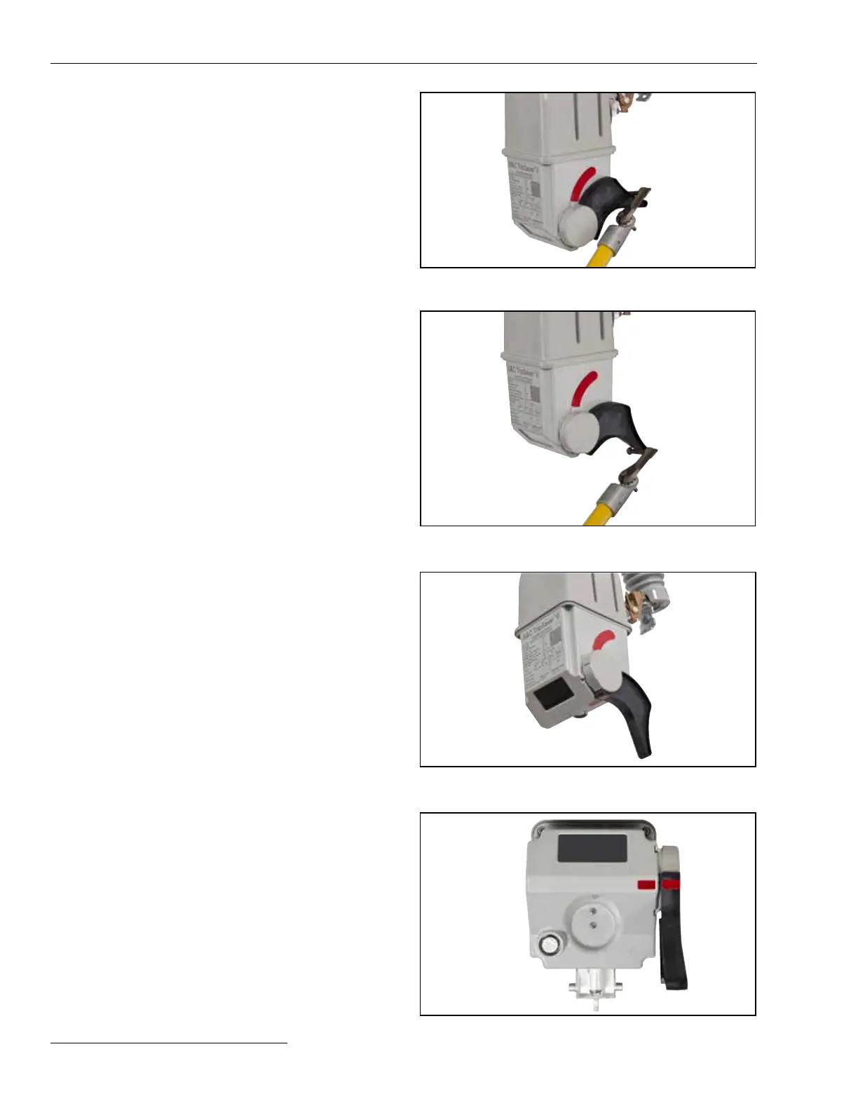
If the MODE-SELECTOR lever is not in the desired
position, reposition it using the straight prong of a Talon
Handling Tool or a distribution prong. See Figure 9 and
Figure 10. Springs help guide the MODE-SELECTOR lever
to the desired position, and labels provide visual guid-
ance. For the Auto position, the upper curved label must
be completely covered. For the NR position, the label on
the lever must align with the label on the lower body. See
Figure 11 and Figure 12.
The operational status of a TripSaver II recloser is
indicated on a nonvolatile liquid-crystal display (LCD)
screen. When the TripSaver II recloser is energized and
the control is powered up, the display screen will show
the most recent status information.
Installation
Figure 12. Labels align when in NR mode.
Figure 11. The lever locks into position and points downward
when in NR mode.
Figure 10. Place the prong under the lever and push up to enter
Auto mode.
Figure 9. Place the prong above the lever and pull down to
enter NR mode.

 Loading...


