S&C Instruction Sheet 461-502 19
Operation
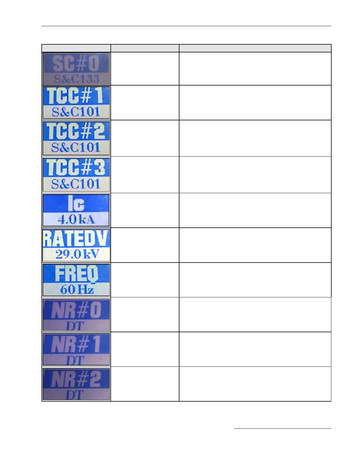
Screen Name Description
SC#0 (Sequence Coordination) Sequence Coordination TCC curve or “Disabled” is displayed.
TCC #1 (Test 1) The short name for the Test 1 curve (2nd TCC curve) is displayed. This
screen is automatically skipped if Test 1 operation is disabled.
TCC #2 (Test 2) The short name for the Test 2 curve (3rd TCC curve) is displayed. This
screen is automatically skipped if Test 2 operation is disabled.
TCC #3 (Test 3) The short name for the Test 3 curve (4th TCC curve) is displayed. This
screen is automatically skipped if Test 3 operation is disabled.
Interrupting Rating The interrupter rating of the recloser, in kA, is displayed.
Max Rated Voltage The rated maximum voltage of the recloser: either 15.5 kV or 29 kV is
displayed.
System Frequency The frequency of the electrical system the TripSaver II recloser is
configured for, in Hz, is displayed.
NR #0 (NR/Remote NR TCC
curve)
This is the Standard NR TCC curve.
NR #1 (Post Fault TCC curve) This is the Post Fault Wakeup NR TCC curve
NR #2 (Cold Wake up TCC
curve)
This is the Cold Wakeup NR TCC curve.
Figure 26. Additional available screens.

 Loading...


