11
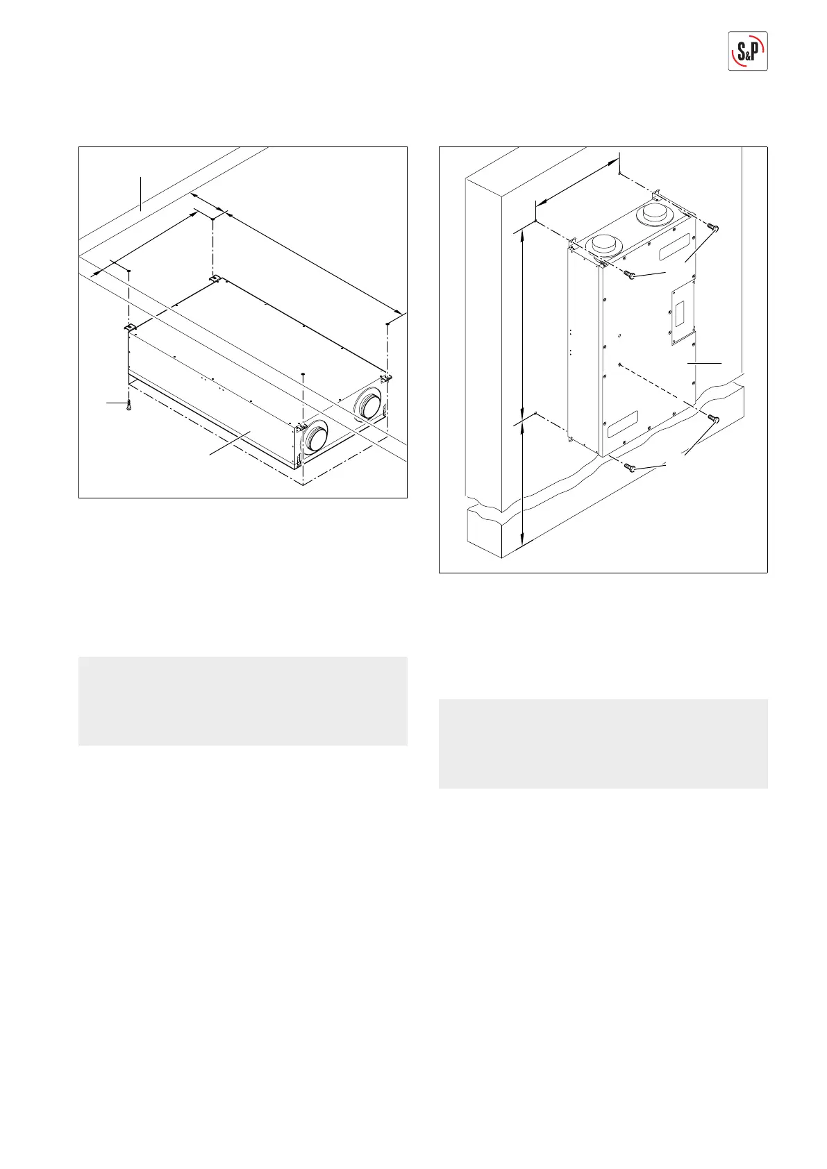
5.2.3. Ceiling installation
1. Drill holes.
A min. 400 mm
B min. 200 mm
C 625 mm
D 1253 mm
2. Position ventilation system (1) with the outside air and
extract air side toward the exterior wall (17) and fasten
with screws (18).
NOTE
Screws (18) are not included in items delivered. Se-
lect screws (18) with appropriate dowels for the bric-
kwork.
5.2.4. Wall installation
1. Drill holes.
A 390 mm (including space needed for condensate
connection)
C 625 mm
D 1253 mm
2. Fasten ventilation system (1) with screws (18).
NOTE
Screws (18) are not included in items delivered. Se-
lect screws (18) with appropriate dowels for the bric-
kwork.
 Loading...