42
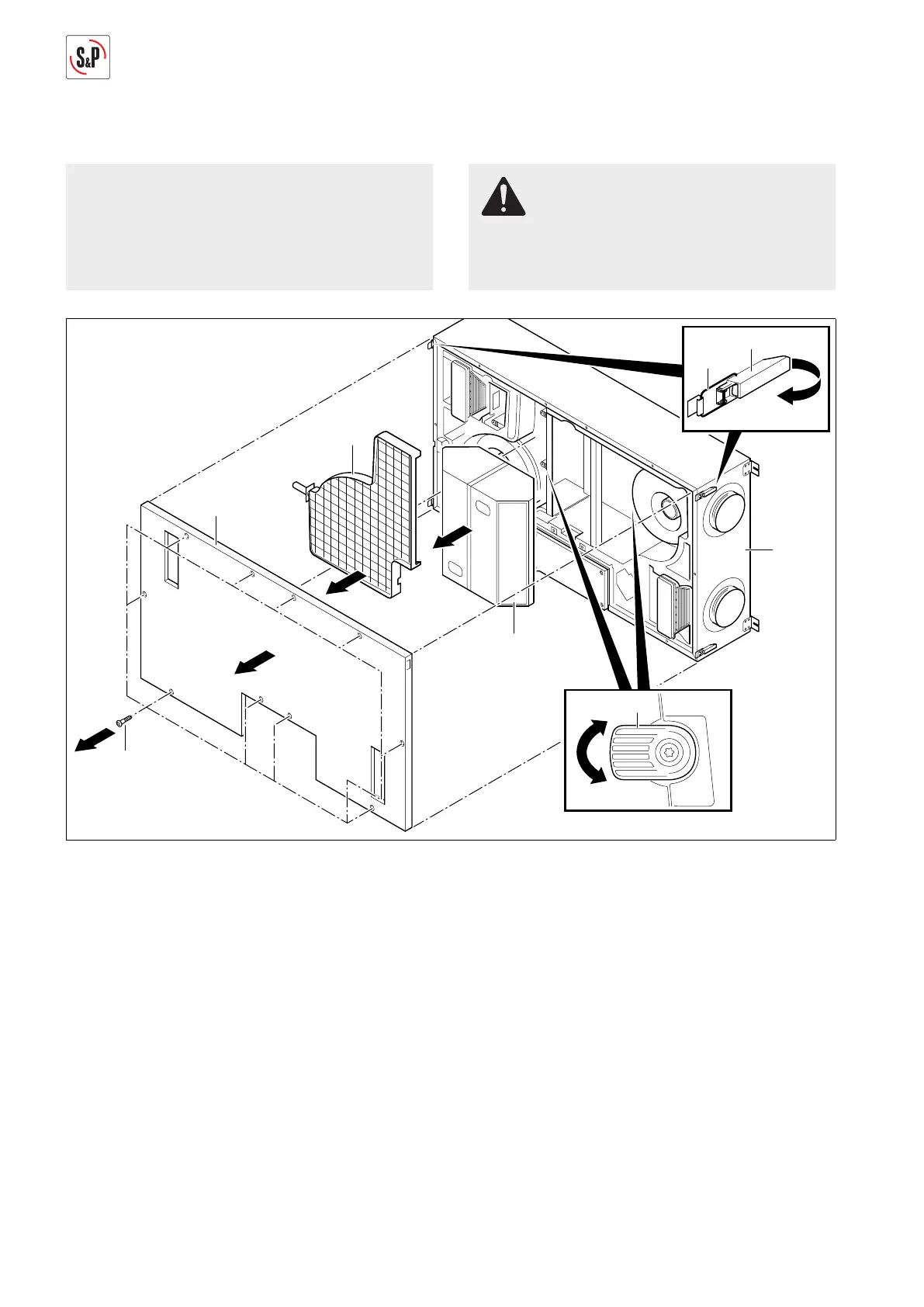
13.2. REPLACING HEAT EXCHANGER
NOTE
The following representations of the ventilation sys-
tem are schematic diagrams. The device is mounted
permanently on the ceiling for all maintenance tas-
ks. The installation position shown is not possible.
RISK OF INJURY
Before replacing the heat exchanger, disconnect all
poles of the ventilation system from the power ne-
twork, otherwise there is risk of injuries.
M
2
M1
6
58
9
57
56
2
1
55
1
3
4
12
59
5
6
M+P-26A-2068
1. Remove screws Torx 25 (55) (Arrow 1).
2. Open all locks (56) and unhook brackets (57) (Arrow 2).
3. Remove cover (58) (Arrow 3).
4. Remove condensate line, see page 12.
5. Take out condensate tray (9) (Arrow 4).
6. Turn quick-release fasteners (59) by 90º to the left or
right (Arrow 5).
7. Take out heat exchanger (12) and replace (Arrow 6).
When replacing, pay attention to the direction of insta-
llation of the heat exchanger (12) (M1/M1, M2/M2).
8. The installation takes place in the reverse sequence.
9. Reconnect condensate line, see page 12.
 Loading...