9
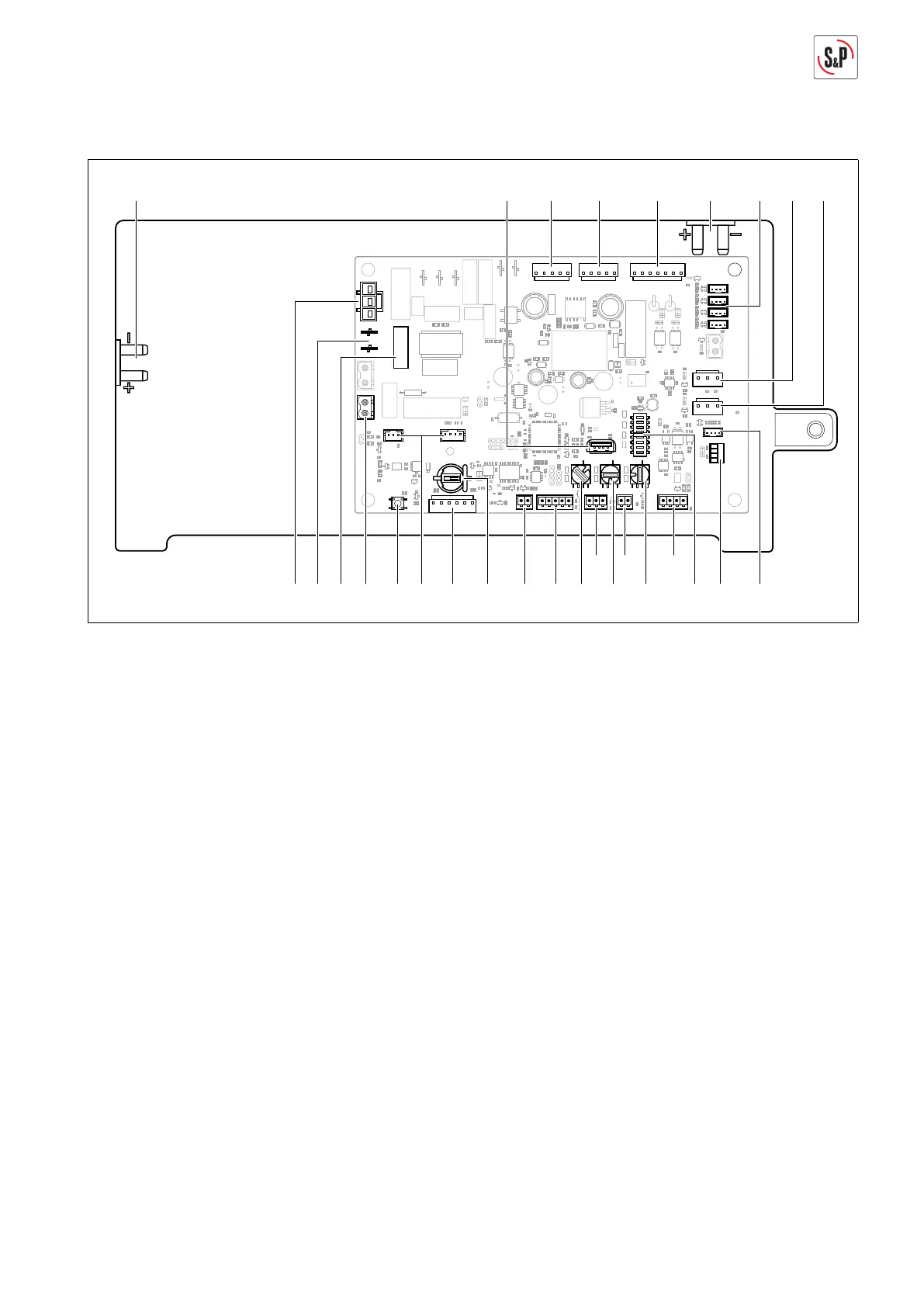
4.7. DIAGRAM MAIN CIRCUIT BOARD
FUSE 5x20
2
1
46 48 49 50 5147 52
3024394142 2735 28
323334
36
37
3138434445
53
54
40
77
7
7
7
30 Connection VOC sensor (optional accessory)
24 Connection control panel
31 Dipswitches for adjusting activating/adjusting
the unit parameters
32 Modbus RTU connection / Connection for
communication module SPCM (optional
accessory)
27 Potentiometer for adjusing the extract air
volume of the unit (factory setting Position 4)
33 External boost contact
28 Potentiometer for adjustment of the ratio
of fl ow rates between supply and extract air
(factory setting Position 0)
34 Connection 0-10 V signal (optional accessory)
35 Potentiometer for target setting of humidity
sensor or VOC sensor (optional accessory)
(factory setting Position A)
36 Connection pressure sensor for constant
pressure mode
37 Contact EMERGENCY SHUTDOWN
38 Button cell type CR1220 for storing time
39 Connection preheating battery (optional
accessory)
40 Connection ServoFlow Kit (optional accessory)
41 Reset (factory setting)
42 Potential-free contact
43 Microfuse F5L250V
44 Harmonics fi lters
45 Voltage supply preheating battery
46 Connection differential pressure gauge for
adjustment of extract airfl ow rate
47 USB connection for software updates
48 Voltage supply M1
49 Voltage supply M2
50 Connection summer bypass
51 Connection differential pressure gauge for
adjustment of conditions fl ow rates (supply air)
52 Connection temperature/humidity sensors
53 Control signals M2
54 Control signals M1
 Loading...