43
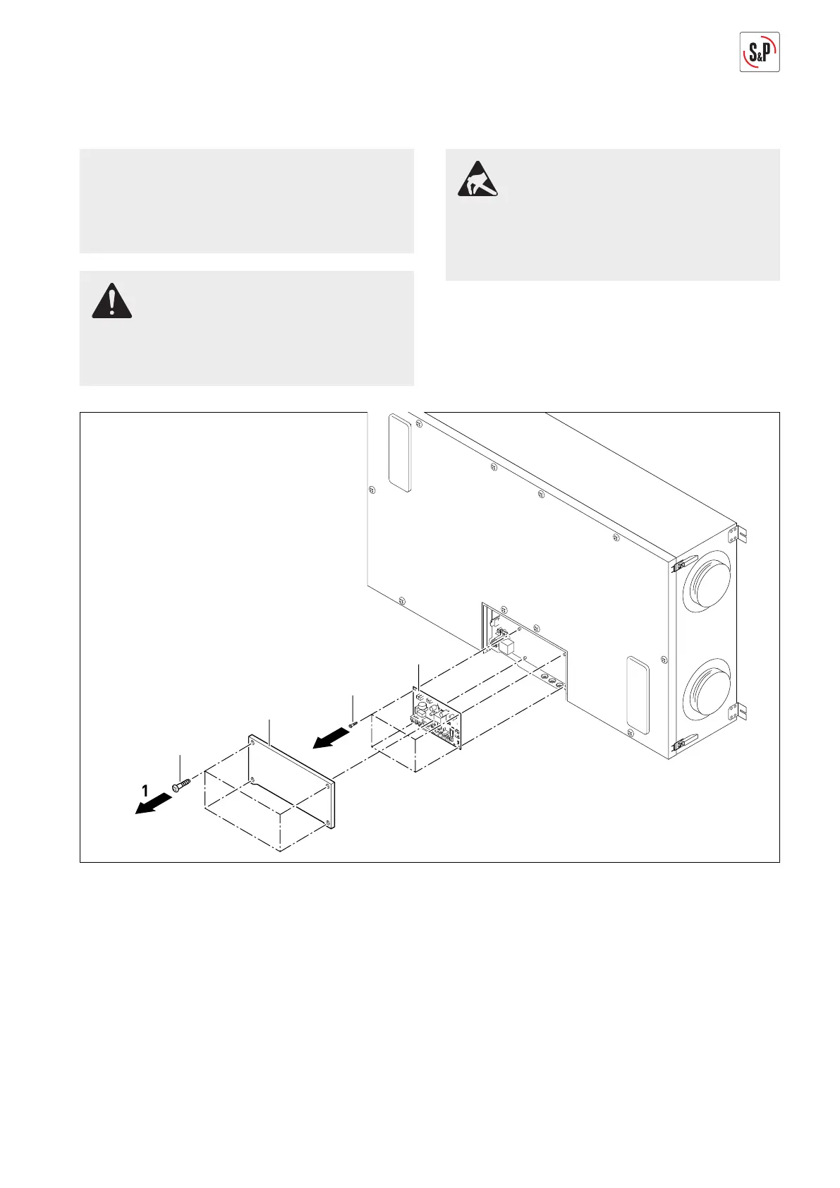
13.3. REPLACING MAIN CIRCUIT BOARDS
NOTE
The following representations of the ventilation sys-
tem are schematic diagrams. The device is mounted
permanently on the ceiling for all maintenance tas-
ks. The installation position shown is not possible.
RISK OF INJURY
Before replacing the heat exchanger, disconnect all
poles of the ventilation system from the power ne-
twork, otherwise there is risk of injuries.
MATERIAL DAMAGES
When replacing the main circuit boards, they must
be protected from electrostatic discharge, otherwise
there is risk of damages. Avoid electric charge in the
body, e.g., by dissipating and earthing of the body.
1. Remove screws Torx 10 (20) and take off cover (21)
(Arrow 1).
2. Disconnect all plugs of the main circuit boards (5).
3. Remove screws Torx 10 (64) and replace main circuit
boards (5) (Arrow 2).
4. Insert all plugs removed into the main circuit boards
(5), see page 9.
5. The installation takes place in the reverse sequence.
 Loading...