37
12.3. CLEANING
RISK OF INJURY
Disconnect all poles of the ventilation system from
the power network before all cleaning tasks, otherwi-
se there is risk of injury.
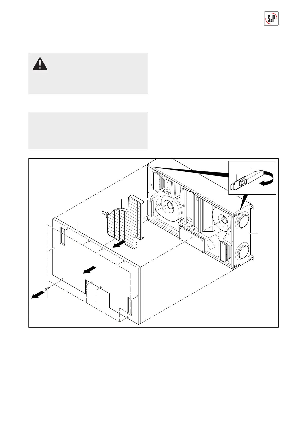
12.3.1. Cleaning ventilation system
NOTE
The following representations of the ventilation sys-
tem are schematic diagrams. The device is mounted
permanently on the ceiling for all maintenance tas-
ks. The installation position shown is not possible.
58
9
57
56
2
1
55
1
3
4
M+P-26A-2067
1. Unscrew screws Torx 25 (55) (Arrow 1).
2. Open all locks (56) and unhook brackets (57) (Arrow 2).
3. Remove cover (58) (Arrow 3).
4. Remove condensate line, see page 12.
5. Take out condensate tray (9) (Arrow 4).
6. Clean interior surfaces of the ventilation device (1) and
condensate connection including condensate tray (9)
with a moist cloth and neutral cleanser.
7. After drying, installation is carried out in the reverse
sequence.
8. Reconnect condensate line, see page 12.
 Loading...