44
13.4. REPLACE HUMIDITY/TEMPERATURE SENSOR
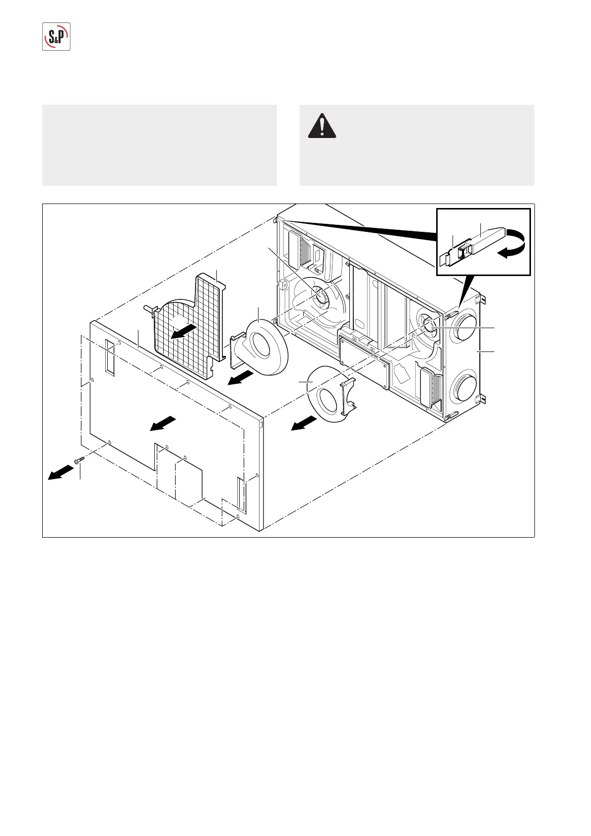
NOTE
The following representations of the ventilation sys-
tem are schematic diagrams. The device is mounted
permanently on the ceiling for all maintenance tas-
ks. The installation position shown is not possible.
RISK OF INJURY
Before replacing the humidity/temperature sensors,
disconnect all poles of the ventilation system from
the power grid, otherwise there is risk of injury.
58
9
57
56
2
1
13
55
1
3
4
60
6
60
5
5
M+P-26A-2069
1. Remove screws Torx 25 (55) (Arrow 1).
2. Open all locks (56) and unhook brackets (57) (Arrow 2).
3. Remove cover (58) (Arrow 3).
4. Remove condensate line, see page 12.
5. Take out condensate tray (9) (Arrow 4).
6. Take off covers (60) (Arrow 5).
 Loading...