38
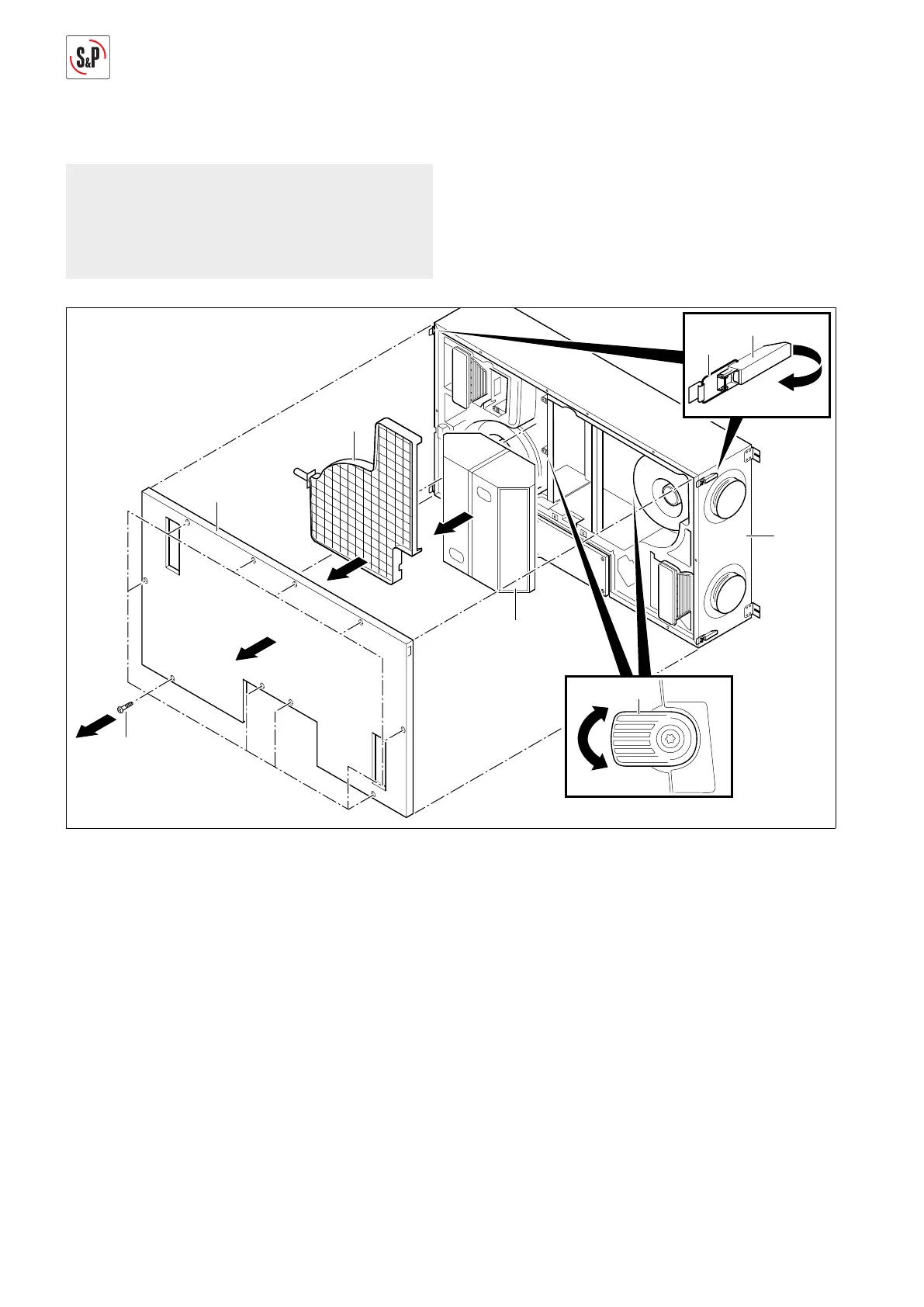
12.3.2. Cleaning heat exchanger
NOTE
The following representations of the ventilation sys-
tem are schematic diagrams. The device is mounted
permanently on the ceiling for all maintenance tas-
ks. The installation position shown is not possible.
M
2
M1
6
58
9
57
56
2
1
55
1
3
4
12
59
5
6
M+P-26A-2068
1. Remove screws Torx 25 (55) (Arrow 1).
2. Open all locks (56) and unhook brackets (57) (Arrow 2).
3. Remove cover (58) (Arrow 3).
4. Remove condensate line, see page 12.
5. Take out condensate tray (9) (Arrow 4).
6. Turn quick-release fasteners (59) by roughly 90º to the
left or right (Arrow 5).
7. Take out heat exchanger (12) (Arrow 6).
8. Clean the heat exchanger (12) using a mixture of water
and soft detergent. Don't use compressed water. Rin-
se with clear water, and allow all water to drain.
9. After drying, installation is carried out in the reverse
sequence. In this process, pay attention to the direc-
tion of installation of the heat exchanger (12) (M1/M1,
M2/M2).
10. Reconnect condensate line, see page 12.
 Loading...