EasyManuals Logo

S&P NEMBUS 210 User Manual

S&P NEMBUS 210
48 pages
To Next Page IconTo Next Page
To Previous Page IconTo Previous Page
Page #41 background imageLoading...
Page #41 background image
41
M
2
M
1
21
5
20
63
62
13
6
48 49
53
54
6
7
8
M+P-26A-2071
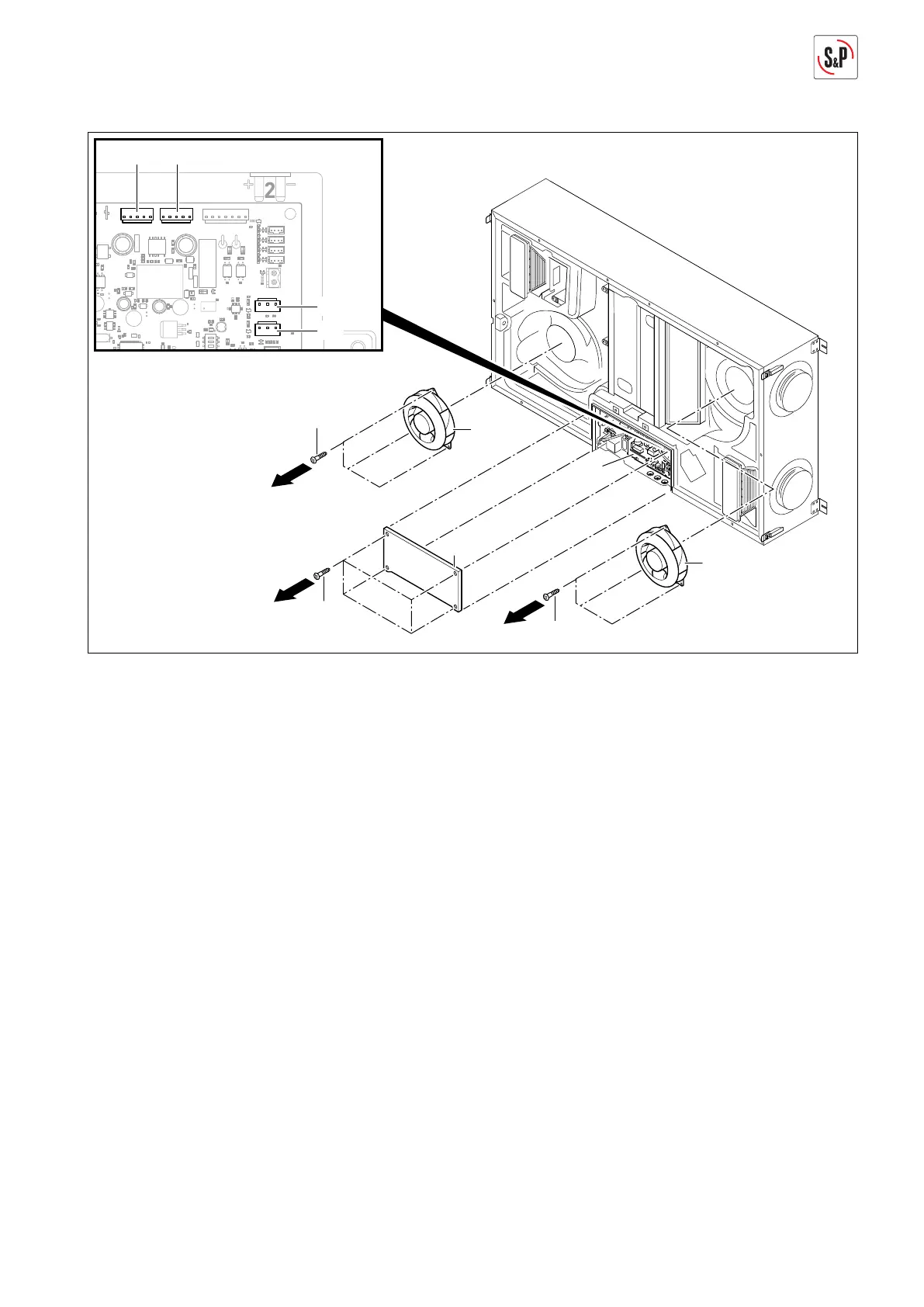
7. Remove screws Torx 10 (20) and take off cover (21)
(Arrow 6).
8. Disconnect voltage supply M1 (48) and M2 (49), as well
as control signals M1 (53) and M2 (54) on the main cir-
cuit board.
9. Remove screws Torx 30 (62) and replace extract air fan
(6) (Arrow 7).
10. Remove screws Torx 30 (63) and replace supply air
fan (13) (Arrow 8).
11. The installation takes place in the reverse sequence.
12. Reconnect condensate line, see page 12.

Table of Contents

Questions and Answers:

Question and Answer IconNeed help?

Do you have a question about the S&P NEMBUS 210 and is the answer not in the manual?

S&P NEMBUS 210 Specifications

General IconGeneral
BrandS&P
ModelNEMBUS 210
CategoryVentilation Hood
LanguageEnglish

Related product manuals