-11-
Mechanical Disassemblies
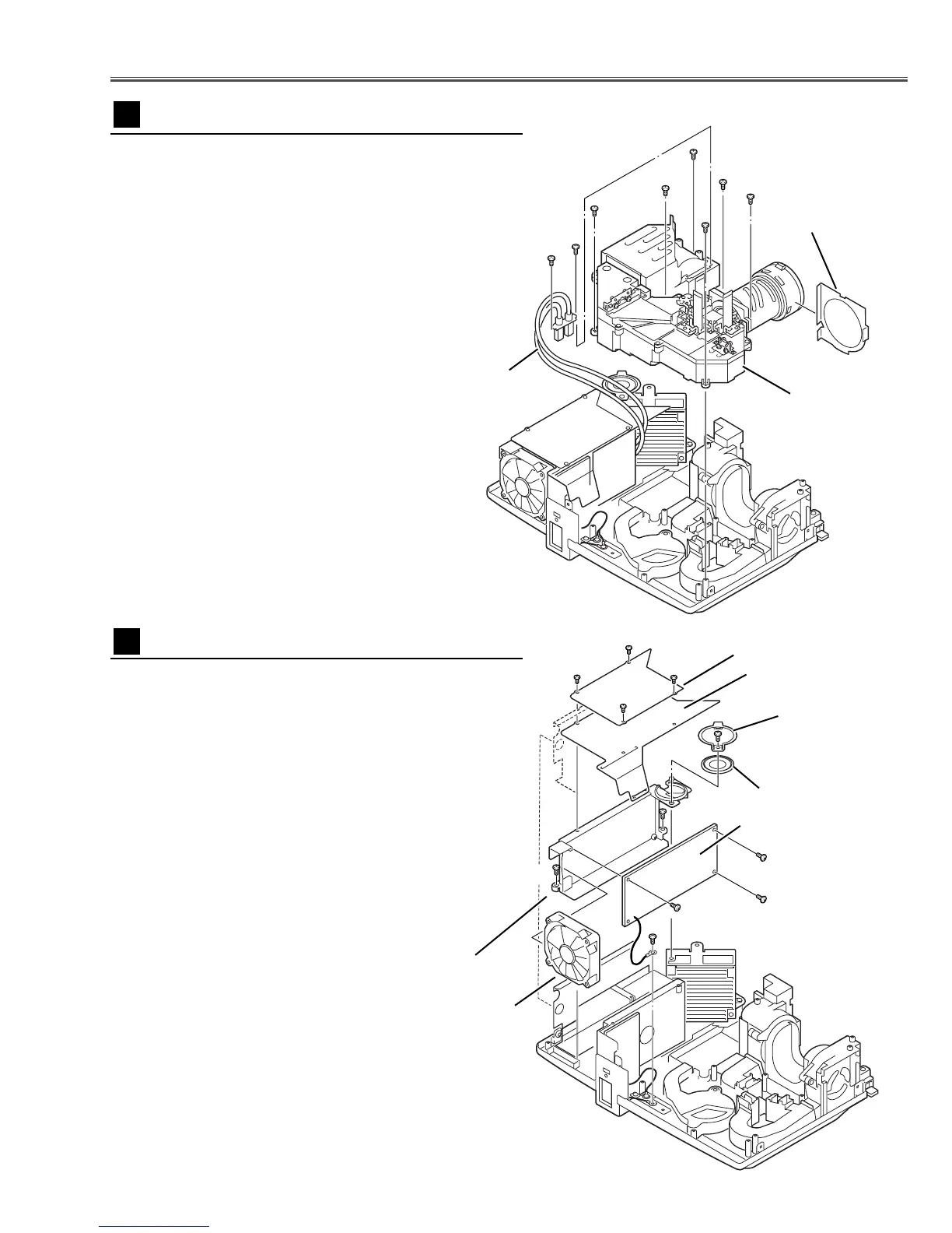
1 Remove 4 screws A (T2x4) to take off the spacer sheet
and the shield plate on the Power Board.
2 Remove 1 screw B (M3x8) to take the Speaker(SP901)
off.
3 Remove 2 screws C (T3x8) and 1 screw D (M4x4) to take
the Power Unit and the Fan(FN906) off.
4 Ta ke the Fan(FN906) from the Holder by pulling it.
5 Remove 3 screws E (T3x6) to take the Power Unit off.
Notes:
You can remove the connectors on the Power Unit
after the Lamp Ballast Unit removal.
Fig.7
Power Unit, Speaker and FN906 removal
7
A
A
A
A
B
E
E
E
D
C
Spacer Sheet
Speaker Holder
Speaker (SP901)
Power Board
FN906
Holder
Fig.6
1 Remove 2 screws A (M3x8) and take the Lamp Cable
off.
2 Remove 6 screws B (T3x10) and take the Optical Unit
upward off.
Optical Unit removal
6
A
A
B
B
B
B
B
B
Optical Unit
Lamp Cable
Shield Plate
C
Cover lens sheet

 Loading...